Blade control device, working machine and blade control method
a blade control and working machine technology, applied in mechanical machines/dredgers, analogue processes for specific applications, instruments, etc., can solve the problem of inevitably forming continuous undulations on the digging surfa
- Summary
- Abstract
- Description
- Claims
- Application Information
AI Technical Summary
Benefits of technology
Problems solved by technology
Method used
Image
Examples
Embodiment Construction
[0026]A bulldozer will be hereinafter explained as an example of “working machine” with reference to the drawings. In the following explanation, “up”, “down”, “front”, “rear”, “left” and “right” are terms defined with reference to an operator seated on an operator seat.
Overall Structure of Bulldozer 100
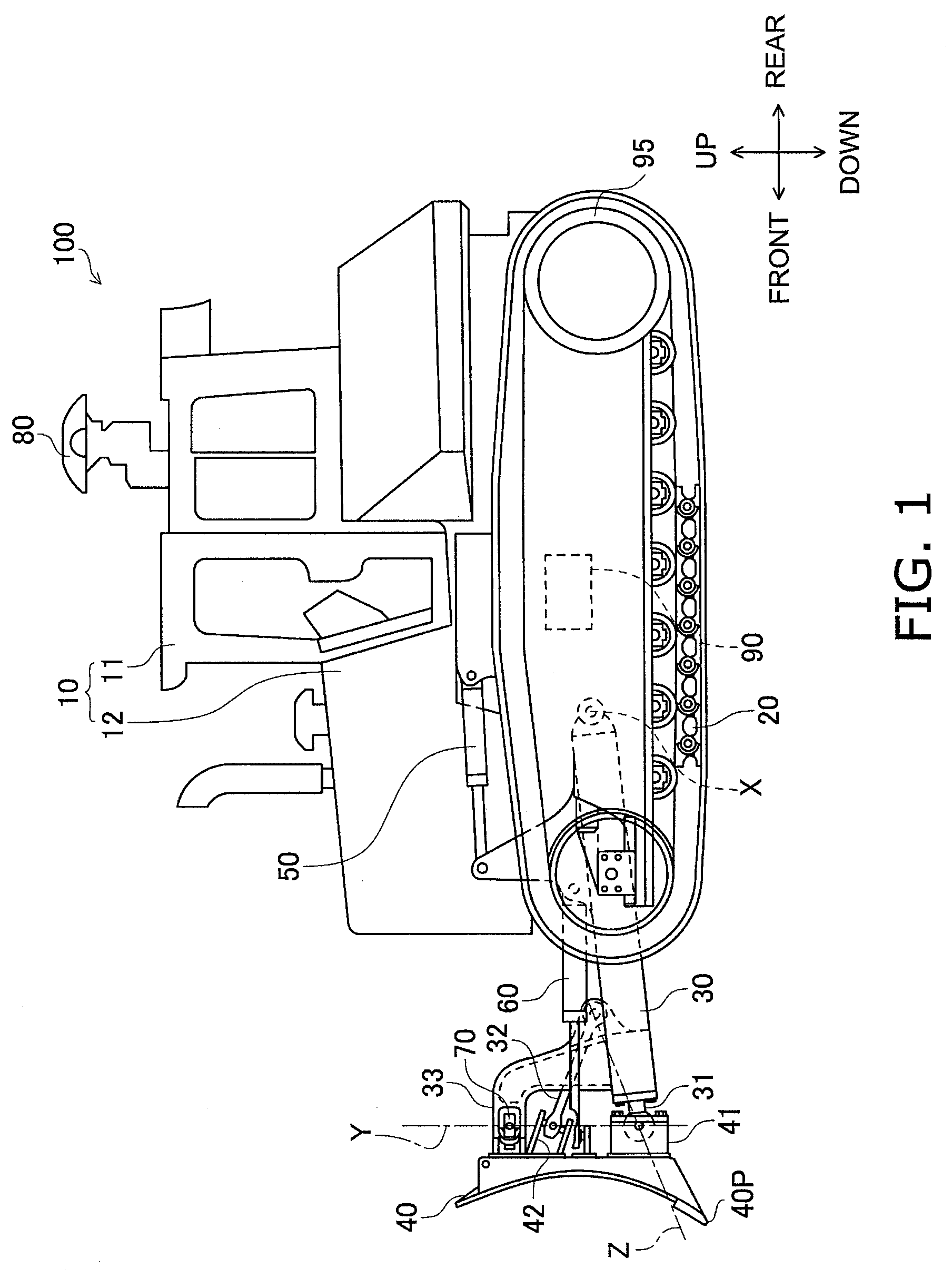
[0027]FIG. 1 is a side view of an entire structure of a bulldozer 100.
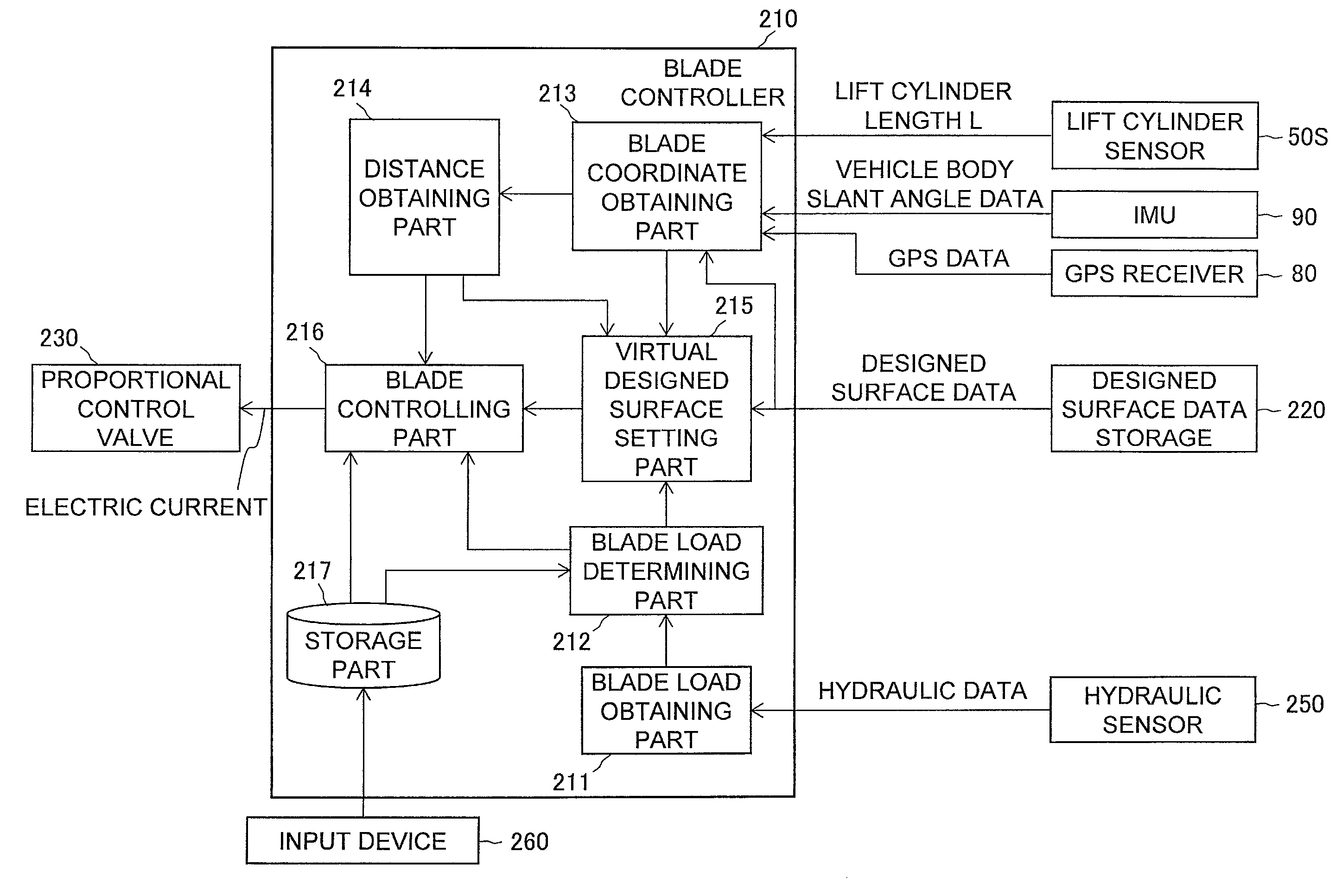
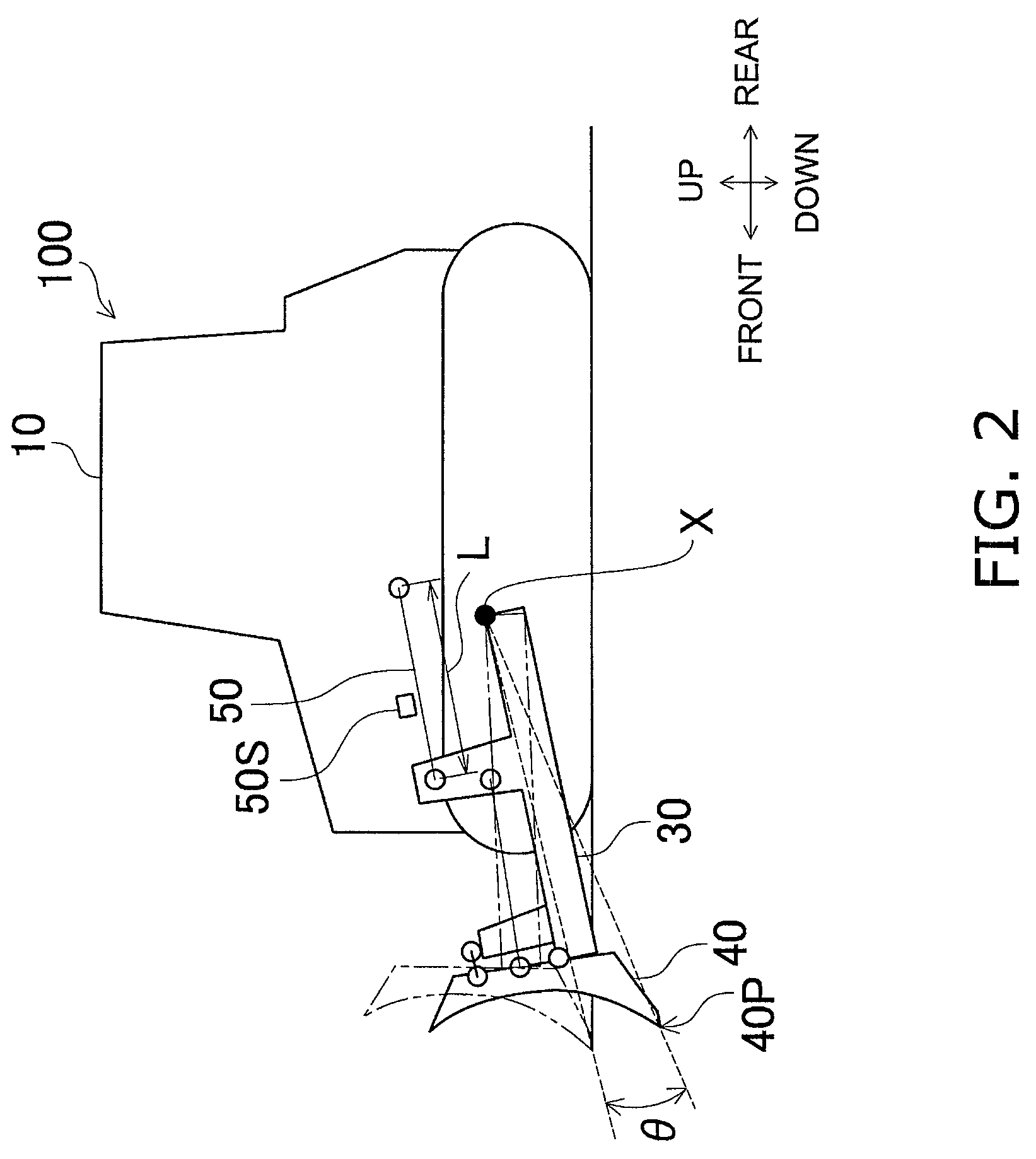
[0028]The bulldozer 100 includes a vehicle body 10, a driving unit 20, a lift frame 30, a blade 40, a lift cylinder 50, an angle cylinder 60, a tilt cylinder 70, a GPS receiver 80, an IMU (Inertial Measurement Unit) 90 and a pair of sprockets 95. Further, the bulldozer 100 is embedded with a blade control device 200 (see FIG. 3). A structure and an action of the blade control device 200 will be described below.
[0029]The vehicle body 10 includes a cab 11 and an engine compartment 12. The operator seat and a variety of operating devices (which are not illustrated in the figures) are installed inside the cab 11. The en...
PUM
 Abstract
Description
Claims
Application Information
 - R&D
- Intellectual Property
- Life Sciences
- Materials
- Tech Scout
- Unparalleled Data Quality
- Higher Quality Content
- 60% Fewer Hallucinations
Browse by: Latest US Patents, China's latest patents, Technical Efficacy Thesaurus, Application Domain, Technology Topic, Popular Technical Reports.
© 2025 PatSnap. All rights reserved.Legal|Privacy policy|Modern Slavery Act Transparency Statement|Sitemap|About US| Contact US: help@patsnap.com


