On-chip loop filter for use in a phase locked loop and other applications

a phase lock and filter technology, applied in the field of phase lock loops, can solve the problem of limited linearity of its components, and achieve the effect of reducing the number of components and reducing the number of transistors

Inactive Publication Date: 2006-07-25
AVAGO TECH WIRELESS IP SINGAPORE PTE
View PDF8 Cites 4 Cited by
  • Summary
  • Abstract
  • Description
  • Claims
  • Application Information

AI Technical Summary

Benefits of technology

[0011]The loop filter of the present invention substantially meets these needs and others. In an embodiment of a phase locked loop that includes such a loop filter, the phase locked loop includes a difference detector, programmable charge pump, fixed loop filter, voltage controlled oscillator and adjustable divider module. The difference detector is operably coupled to determine a different signal based on differences in phase and / or frequency between a reference oscillation and a feedback oscillation. The programmable charge pump is operably coupled to generate a charge current based on the difference signal and a scaling signal. The fixed loop filter is operably coupled to convert the charge current into a control voltage. The voltage controlled oscillator generates an output oscillation based on the control voltage and the adjustable divider module generates the feedback oscillation based on the output oscillation and a divider value. The scaling module is operably coupled to produce the scaling signal based on the selected divider. Accordingly, by scaling the charge current in accordance with the divider value, fixed components may be used for the loop filter and still provide the desired frequency response for various divider values. As such, a loop filter may readily be implemented on an integrated circuit and require a relatively some amount of die area.

Problems solved by technology

While a fractional-N synthesizer allows for fine-tuning of the local oscillator, its accuracy is limited by the linearity of its components.

Method used


Image

  • On-chip loop filter for use in a phase locked loop and other applications
  • On-chip loop filter for use in a phase locked loop and other applications
  • On-chip loop filter for use in a phase locked loop and other applications

Examples


Embodiment Construction

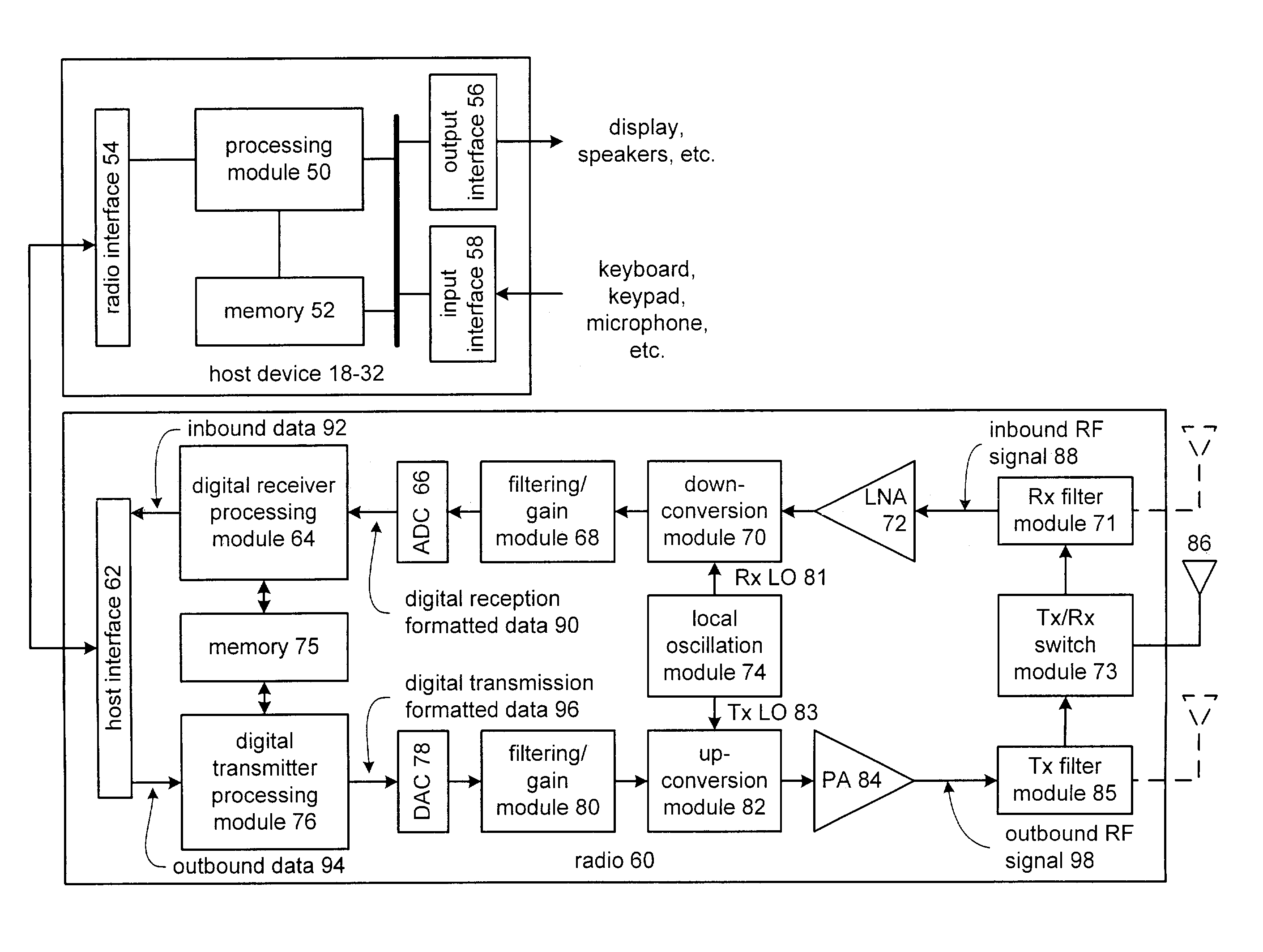
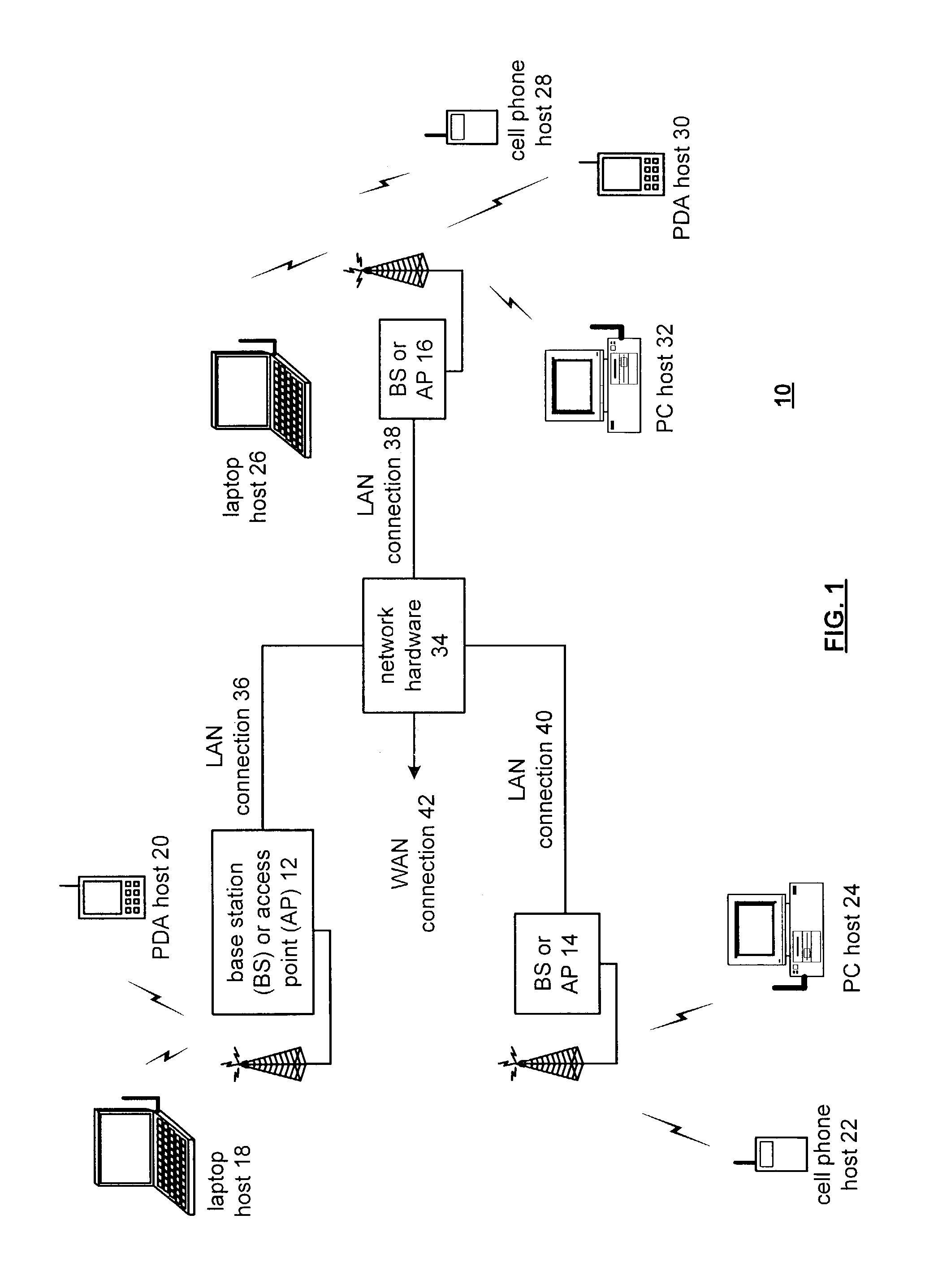
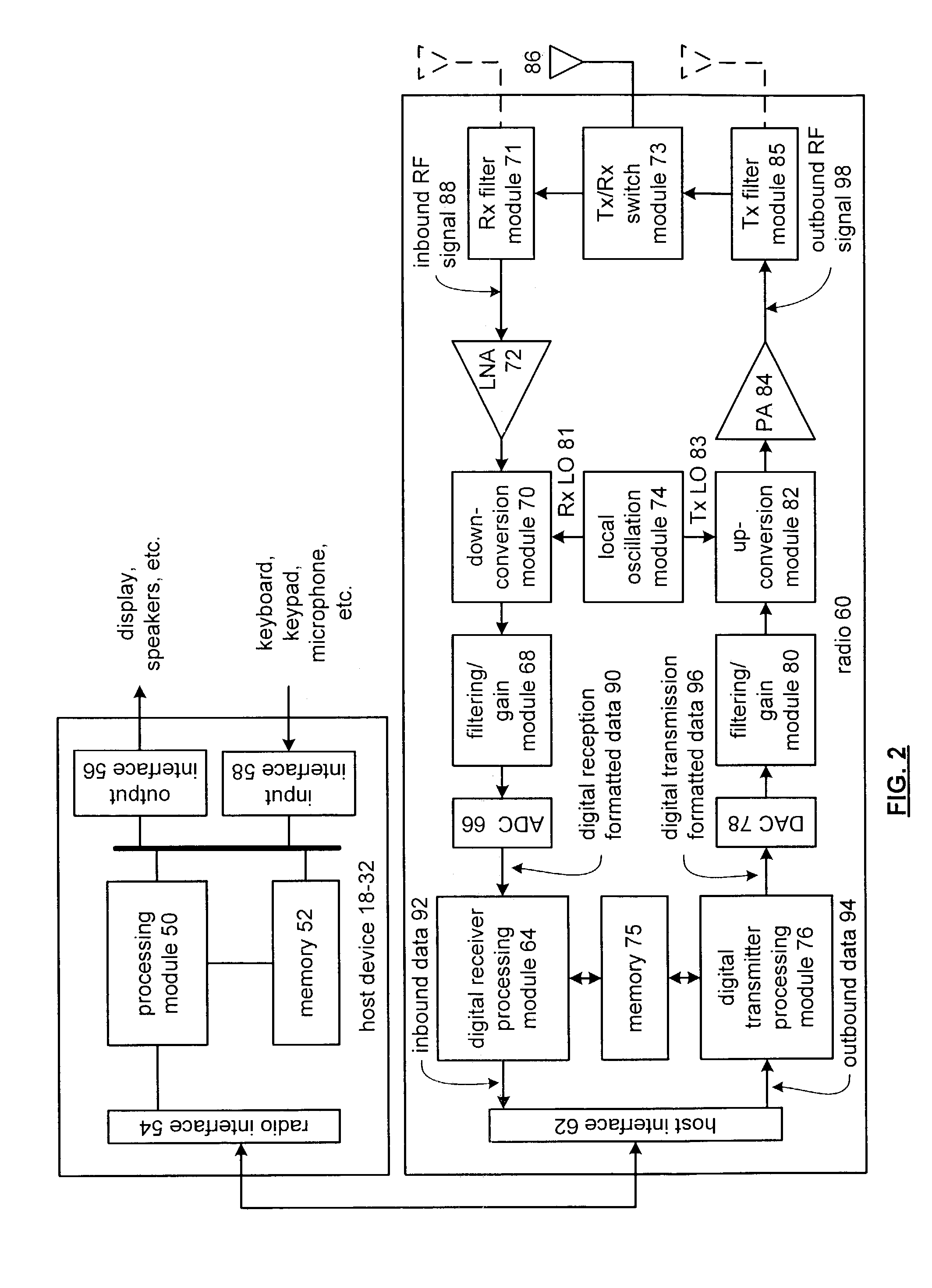
[0018]FIG. 1 is a schematic block diagram illustrating a communication system 10 that includes a plurality of base stations and / or access points 12–16, a plurality of wireless communication devices 18–32 and a network hardware component 34. The wireless communication devices 18–32 may be laptop host computers 18 and 26, personal digital assistant hosts 20 and 30, personal computer hosts 24 and 32 and / or cellular telephone hosts 22 and 28. The details of the wireless communication devices will be described in greater detail with reference to FIG. 2.

[0019]The base stations or access points 12–16 are operably coupled to the network hardware 34 via local area network connections 36, 38 and 40. The network hardware 34, which may be a router, switch, bridge, modem, system controller, et cetera provides a wide area network connection 42 for the communication system 10. Each of the base stations or access points 12–16 has an associated antenna or antenna array to communicate with the wirele...


PUM


Abstract

A phase locked loop that includes such a loop filter, the phase locked loop includes a difference detector, programmable charge pump, fixed loop filter, voltage controlled oscillator and adjustable divider module. The difference detector is operably coupled to determine a different signal based on differences in phase and / or frequency between a reference oscillation and a feedback oscillation. The programmable charge pump is operably coupled to generate a charge current based on the difference signal and a scaling signal. The fixed loop filter is operably coupled to convert the charge current into a control voltage. The voltage controlled oscillator generates an output oscillation based on the control voltage and the adjustable divider module generates the feedback oscillation based on the output oscillation and a divider value. The scaling module is operably coupled to produce the scaling signal based on the selected divider.

Description

BACKGROUND OF THE INVENTION[0001]1. Technical Field of the Invention[0002]This invention relates generally to mixed signal circuitry and more particularly to phase locked loops.[0003]2. Description of Related Art[0004]Communication systems are known to support wireless and wire lined communications between wireless and / or wire lined communication devices. Such communication systems range from national and / or international cellular telephone systems to the Internet to point-to-point in-home wireless networks. Each type of communication system is constructed, and hence operates, in accordance with one or more communication standards. For instance, wireless communication systems may operate in accordance with one or more standards including, but not limited to, IEEE 802.11, Bluetooth, advanced mobile phone services (AMPS), digital AMPS, global system for mobile communications (GSM), code division multiple access (CDMA), local multi-point distribution systems (LMDS), multi-channel-multi...

Claims


Application Information

Patent Timeline
Patent Type & Authority Patents(United States)
IPC IPC(8): H04M1/66H03L7/089H03L7/093H03L7/197H04B1/00
CPCH03L7/0891H03L7/0898H03L7/1976H03L7/093H03L2207/04
Inventor CHIEN, HUNG-MING
Owner AVAGO TECH WIRELESS IP SINGAPORE PTE
Why Eureka
Try Eureka