System and method for remotely identifying display components

a technology of display components and remote identification, applied in the field of system and method for remotely identifying display components, can solve problems such as premature failure of one or more components, and deformation of the display

Inactive Publication Date: 2015-05-05
MFG RESOURCES INT INC
View PDF15 Cites 21 Cited by
  • Summary
  • Abstract
  • Description
  • Claims
  • Application Information

AI Technical Summary

Benefits of technology

[0008]An exemplary embodiment may place local storage devices at one or more components within the display, which can be read remotely to determine exactly what piece of hardware (or sometimes software) was installed with any particular component. Thus, if software updates are being considered, a user can check to determine if the hardware can support the software update. Further, if a particular piece of hardware has been found to be prone to failure, the displays which contain this hardware can be located and serviced without having to open and inspect every display to find which ones contain the particular piece of hardware. In some embodiments the local storage devices can also store important performance data such as maximum temperature and / or current draw. This data can provide valuable feedback when diagnosing performance issues / problems and troubleshooting failures.

Problems solved by technology

Over many hours of use, even the most reliable electronic displays are know to degrade in performance or possibly have one or more components fail prematurely.
When a display is used for advertising purposes, a sudden failure or degradation in performance can result in the loss of critical advertising exposure and a possible loss of revenue to the advertising firm.
Further, when a display is used for information, a failure of the display may result in the loss of critical information such as flight schedules or emergency alerts.

Method used


Image

  • System and method for remotely identifying display components
  • System and method for remotely identifying display components
  • System and method for remotely identifying display components

Examples


Embodiment Construction

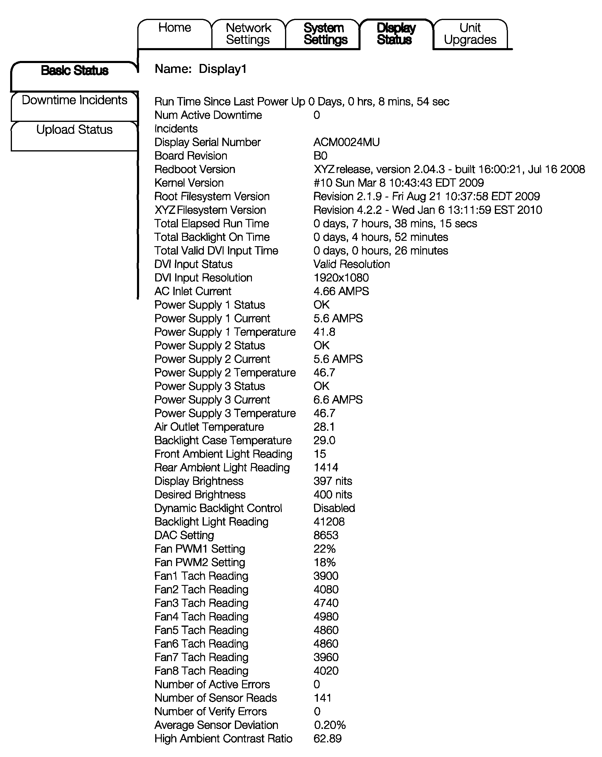
[0006]Exemplary embodiments provide communication between one or more displays with a user through an internet or network connection. In some embodiments this communication would be two-way communication. Electronic data may be sent from one or more displays to a user for monitoring the displays, ensuring adequate performance for the customer, gathering data for reliability research and analysis, as well as diagnosing and possibly fixing some display problems remotely.

[0007]Exemplary embodiments may display a predetermined watermark on the display and measure the characteristics of the watermark through one or more color light sensors which are embedded within the display. The color light sensor provides feedback data regarding any number of performance characteristics of the display. The data may be stored internally within the display for a certain amount of time (or until the local storage is full) and may be sent to a user remotely when requested. The data can indicate failures ...


PUM


Abstract

A system and method for remotely-identifying the components and / or software revisions within an electronic display. An electronic storage device may be placed within an electronic display assembly and placed in electrical communication with a network connection. The electronic storage device may contain identification numbers for one or more components or software revisions within the display. A computing device may be in electrical communication with the network connection so that the identification numbers on the electronic storage device may be accessed remotely. If a particular component or software revision is desired, the computing device may be used to search the contents of each electronic storage device at each display to determine which displays contain the desired component or software revision.

Description

CROSS-REFERENCE TO RELATED APPLICATIONS[0001]This application is a non-provisional of U.S. Application No. 61 / 312,892 filed Mar. 11, 2010 and is hereby incorporated by reference as if fully cited herein. This application is a continuation in part of U.S. application Ser. No. 12 / 763,797 filed Apr. 20, 2010 and is hereby incorporated by reference as if fully cited herein. This application is a continuation in part of U.S. application Ser. No. 12 / 986,787 filed Jan. 7, 2011 which is a non-provisional of U.S. Application No. 61 / 308,139 filed Feb. 25, 2010 each of which are hereby incorporated by reference as if fully cited herein. This application is a continuation in part of U.S. application Ser. No. 12 / 706,594 filed Feb. 16, 2010 which is a non-provisional of U.S. Application No. 61 / 152,876 filed Feb. 16, 2009 each of which are hereby incorporated by reference as if fully cited herein. This application is a continuation in part of U.S. application Ser. No. 12 / 706,602 filed Feb. 16, 201...

Claims


Application Information

Patent Timeline
Patent Type & Authority Patents(United States)
IPC IPC(8): G06F3/00G06F3/0489G06F3/14H04N17/04H04N21/00
CPCH04N17/04G06F3/04897H04N21/00G06F3/1454G09G2320/08
Inventor DUNN, WILLIAMDE LAET, RICK
Owner MFG RESOURCES INT INC
Why Eureka
Try Eureka