Compound engine system with rotary engine

a technology of compound engine and rotary engine, which is applied in the direction of machines/engines, liquid fuel engines, rotary/oscillating piston pump components, etc., can solve the problem that engines may not be fully optimized for use in turbocompounding systems

Active Publication Date: 2015-05-12
PRATT & WHITNEY CANADA CORP
View PDF40 Cites 25 Cited by
  • Summary
  • Abstract
  • Description
  • Claims
  • Application Information

AI Technical Summary

Benefits of technology

[0006]In another aspect, there is provided a method of improving combustion stability of a compound engine system including at least one rotary engine having rotating chambers each having a volume varying between a minimum volume and a maximum volume, the method comprising positioning inlet and outlet ports of the rotary engine such that the rotary engine has a volumetric compression ratio lower than a volumetric expansion ratio thereof, and sizing a portion of each of the chambers defined in a rotor of the rotary engine such that the portion defines more than 5% of a difference between the maximum and minimum volumes.

Problems solved by technology

However, such engines may not be fully optimized for use in turbocompounding systems, and thus room for improvement exists.

Method used


Image

  • Compound engine system with rotary engine
  • Compound engine system with rotary engine
  • Compound engine system with rotary engine

Examples


Embodiment Construction

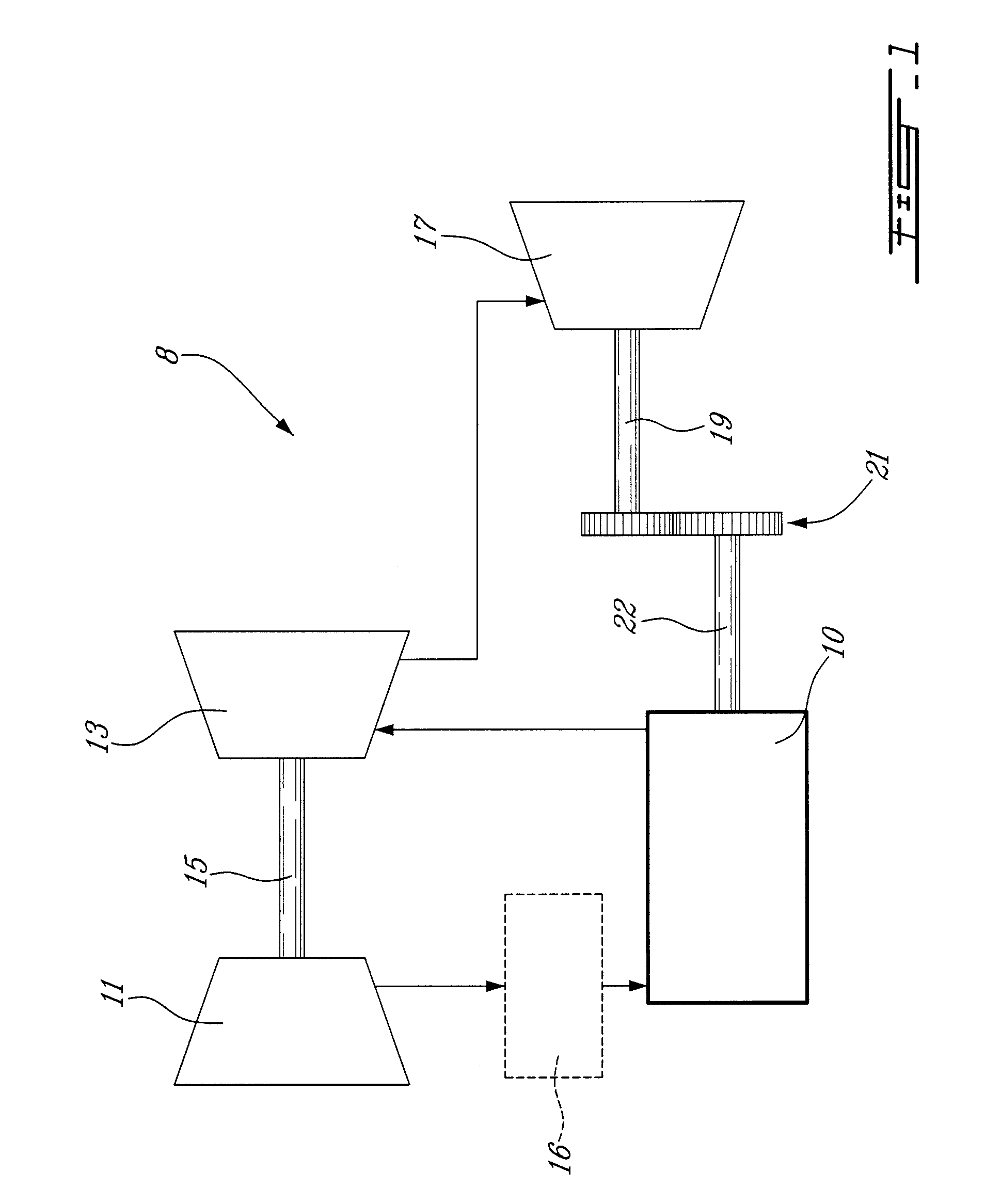
[0012]Referring now to FIG. 1, a compound engine system 8 is schematically shown. The system 8 includes a compressor 11 and a turbine 13 which are connected by a shaft 15, and which act as a turbocharger to one or more rotary engines 10. The compressor 11 may be a single-stage or multiple-stage centrifugal device and / or an axial device. A rotary engine 10, or a plurality of rotary engines, receives compressed air from the compressor 11. The air optionally circulates through an intercooler 16 between the compressor 11 and the rotary engine(s) 10.

[0013]The exhaust gas exiting the rotary engine 10 is supplied to the compressor turbine 13 and also to a power turbine 17, the turbines 13, 17 being shown here in series, i.e. with the exhaust gas flowing first through one of the two turbines where the pressure is reduced, and then through the other turbine, where the pressure is further reduced. In an alternate embodiment (not shown), the turbines 13, 17 are arranged in parallel, i.e. with ...


PUM

PropertyMeasurementUnit
volumetric compression ratioaaaaaaaaaa
volumeaaaaaaaaaa
volumesaaaaaaaaaa

Abstract

A compound engine system comprising a rotary engine having a volumetric compression ratio lower than its volumetric expansion ratio, and a recess defined in the peripheral wall of the rotor in each of the chambers having a volume of more than 5% of the displacement volume of the chamber. The expansion in the turbine section compensates for the relatively low expansion ratio of the rotary engine.

Description

CROSS-REFERENCE TO RELATED APPLICATION[0001]This application claims priority on provisional U.S. application No. 61 / 512,570 filed Jul. 28, 2011, the entire contents of which are incorporated by reference herein.TECHNICAL FIELD[0002]The application relates generally to a compound engine system including a rotary internal combustion engine.BACKGROUND OF THE ART[0003]Rotary engines, such as for example Wankel engines, use the eccentric rotation of a piston to convert pressure into a rotating motion, instead of using reciprocating pistons. In these engines, the rotor includes a number of apex or seal portions which remain in contact with a peripheral wall of the rotor cavity of the engine throughout the rotational motion of the rotor to create a plurality of rotating chambers when the rotor rotates.[0004]In a never-ending quest to achieve greater power output, Wankel engines have relatively low rotor recess volume in order to achieve the high volumetric expansion ratio required for such...

Claims


Application Information

Patent Timeline
Patent Type & Authority Patents(United States)
IPC IPC(8): F02G3/00F02B53/08F02B53/10F02B33/44F02B33/00F01C1/02F01C1/22F01C11/00F01C20/06F01C20/10F01C20/24F01C21/06F01C21/08F01C21/10F01C21/18F04C29/00
CPCF01C1/22F01C11/006F01C21/08F01C21/18F01C20/06F01C20/10F01C20/24F01C21/06F01C21/106F01C21/183F04C29/0092F04C2240/20F04C2240/80Y10T29/49234F02B37/00Y02T10/12F02B55/02F02B55/14
Inventor JULIEN, ANDRE
Owner PRATT & WHITNEY CANADA CORP
Why Eureka
Try Eureka