Decanter centrifuge with energy recovery structure
a technology of energy recovery structure and centrifuge, which is applied in the direction of centrifuges, rotary centrifuges, etc., can solve the problems of energy loss, energy consumed, energy loss, etc., and achieve the effect of optimizing energy recovery, reducing wet surface of channel, and reducing energy loss
- Summary
- Abstract
- Description
- Claims
- Application Information
AI Technical Summary
Benefits of technology
Problems solved by technology
Method used
Image
Examples
first embodiment
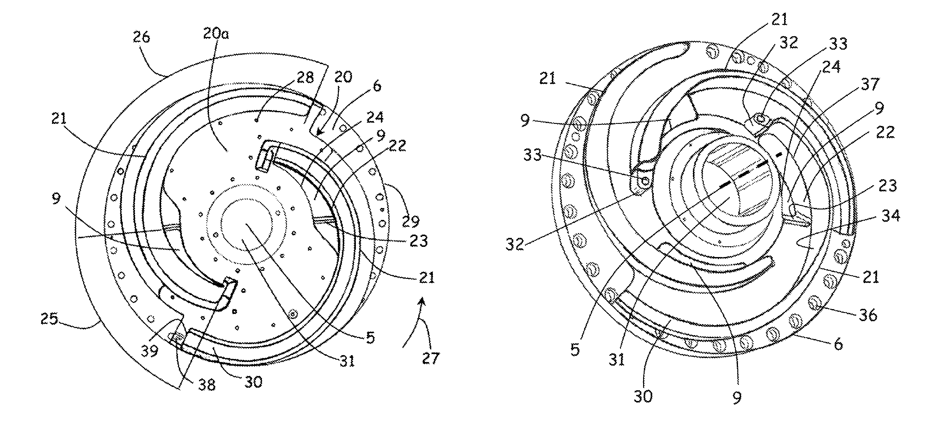
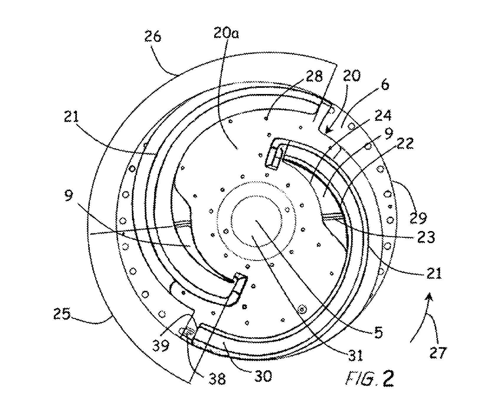
[0035]Turning to FIG. 2 a base plate 6 of a decanter centrifuge 1 is shown. The base plate 6 is equipped with a decanter centrifuge discharge member 20 according to the invention mounted on the base plate such that the axis of rotation 5 extends through a central opening 31. The decanter centrifuge discharge member 20 may be mounted using screws or the like inserted through first holes 28. Alternatively, the decanter centrifuge discharge member 20 may be mounted on a decanter centrifuge discharge member base plate (not shown) similar to the base plate 6 shown in FIG. 2 that may then be mounted on the base plate 6 of the decanter centrifuge 1. For mounting the decanter centrifuge discharge member base plate there may be provided holes such as second holes 36. However, in the embodiment shown the second holes 36 are used to mount the base plate 6 on the decanter centrifuge 1. As another alternative the decanter centrifuge discharge member 20 may simply be cast or moulded in one piece ...
second embodiment
[0047]FIG. 5 features the base plate 6 seen from below having three outlet openings 9, each with a circumferential edge substantially as described above. On the base plate 6 is provided a slide valve body 40 in one piece comprising three openings 45 corresponding in shape and orientation to the outlet openings 9. Alternatively there may be provided a separate slide valve body for each outlet opening in the base plate 6.
[0048]The slide valve body is in FIG. 5 shown in its open position, the outlet openings 9 being completely free. The slide valve body 40 is mounted such as to be able to rotate around the axis of rotation. Furthermore the slide valve body 40 may comprise adjustment means (not shown) for sliding or rotating the slide valve body 40. Such an adjustment means is preferably a, preferably automatic, drive means, but may also be e.g. a manual adjustment means.
[0049]Furthermore, the slide valve body 40 comprises a level sensor comprising two sensor elements 42a, 42b. The sen...
PUM
 Abstract
Description
Claims
Application Information
 - R&D
- Intellectual Property
- Life Sciences
- Materials
- Tech Scout
- Unparalleled Data Quality
- Higher Quality Content
- 60% Fewer Hallucinations
Browse by: Latest US Patents, China's latest patents, Technical Efficacy Thesaurus, Application Domain, Technology Topic, Popular Technical Reports.
© 2025 PatSnap. All rights reserved.Legal|Privacy policy|Modern Slavery Act Transparency Statement|Sitemap|About US| Contact US: help@patsnap.com


