
Piezoelectric vibrating piece, piezoelectric vibrator, oscillator, electronic apparatus and radio controlled timepiece

a piezoelectric vibrating and piezoelectric technology, applied in piezoelectric/electrostrictive/magnetostrictive devices, oscillators, oscillators, etc., can solve problems such as vibration leakage (leakage of vibration energy) and achieve the effect of suppressing vibration leakage and improving performan

Active Publication Date: 2015-05-12
SII CRYSTAL TECH
View PDF13 Cites 1 Cited by
  • Summary
  • Abstract
  • Description
  • Claims
  • Application Information

AI Technical Summary

Benefits of technology

This design effectively reduces vibration leakage, stabilizes the resonance frequency, and allows for a reduced size of the piezoelectric vibrating piece while maintaining a desired frequency, preventing an increase in the package width dimension.

Problems solved by technology

However, when operating the piezoelectric vibrating piece, it is known that vibration leakage (leakage of vibration energy) occurs from the mount section of the base section to the side of the package.

Method used


Image

  • Piezoelectric vibrating piece, piezoelectric vibrator, oscillator, electronic apparatus and radio controlled timepiece
  • Piezoelectric vibrating piece, piezoelectric vibrator, oscillator, electronic apparatus and radio controlled timepiece
  • Piezoelectric vibrating piece, piezoelectric vibrator, oscillator, electronic apparatus and radio controlled timepiece

Examples


embodiments

Configuration of Piezoelectric Vibrator

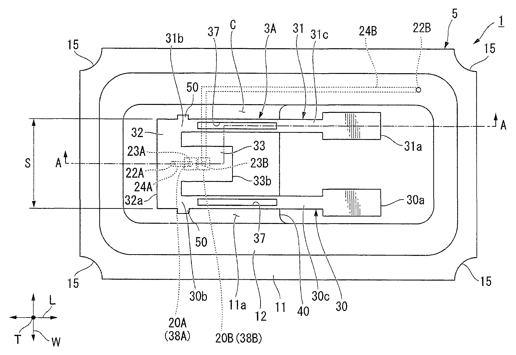
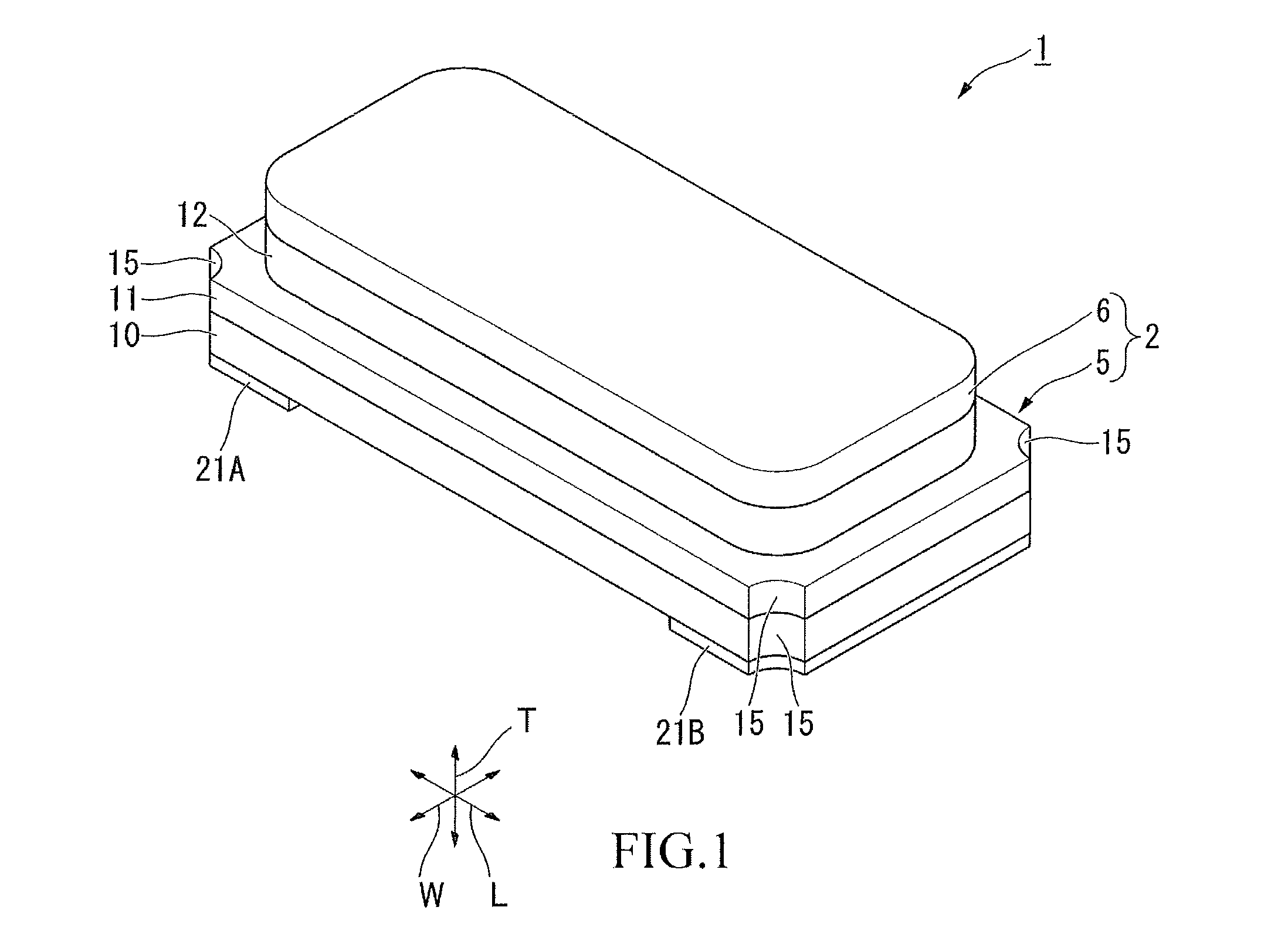
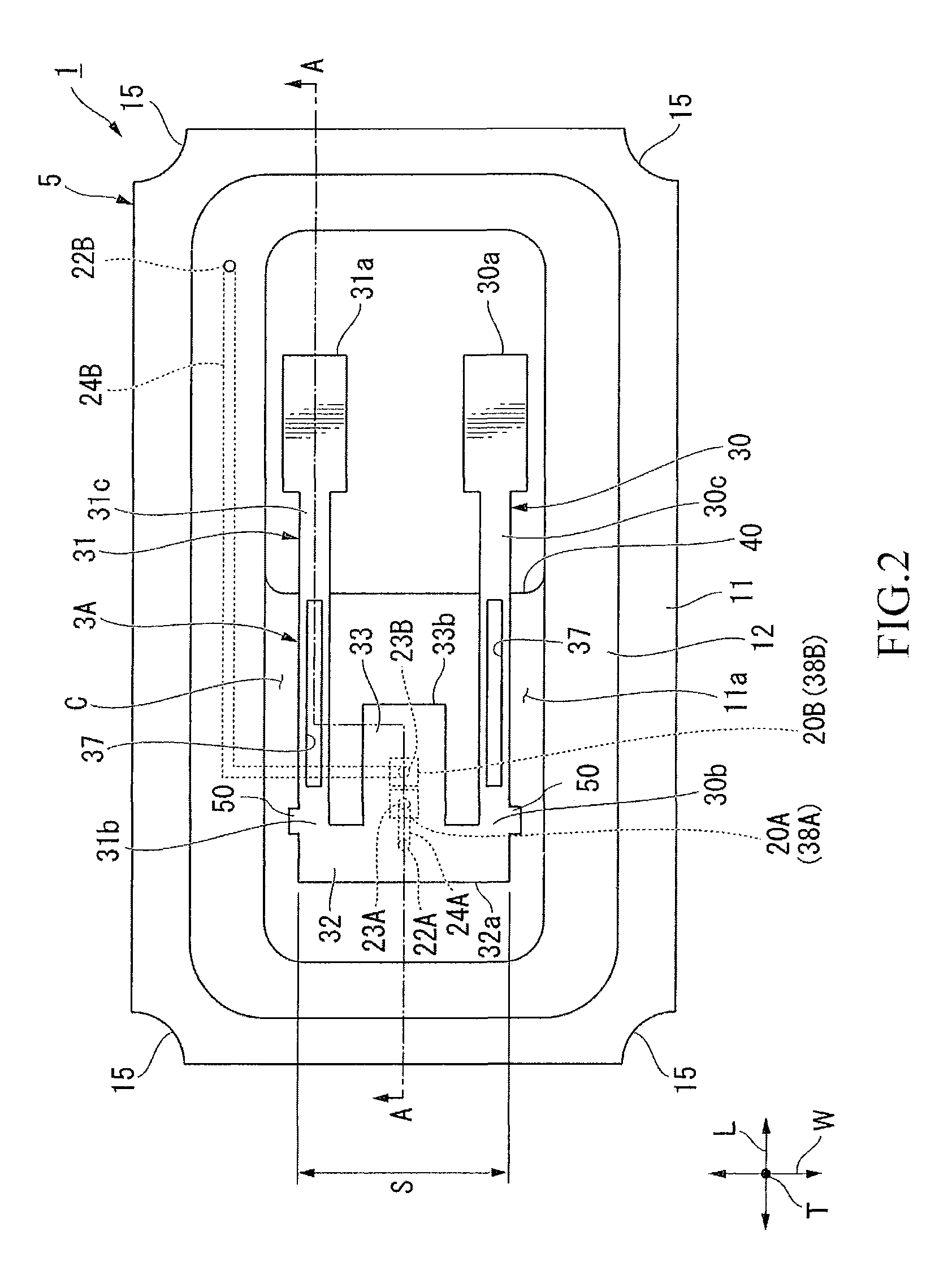
[0034]As illustrated in FIGS. 1 to 4, a piezoelectric vibrator 1 of the embodiment is a surface mounting vibrator of a ceramic package type including a package 2 having a cavity C that is hermetically sealed on the inside thereof and a tuning fork type piezoelectric vibrating piece 3A accommodated in the cavity C.

[0035]The piezoelectric vibrator 1 is formed in a substantially rectangular parallelepiped shape and a longitudinal direction of the piezoelectric vibrator 1 is referred to as a length direction L, a short direction is referred to as a width direction W, and a direction orthogonal to the length direction L and the width direction W is referred to as a thickness direction T in a plan view in the embodiment.

[0036]The package 2 includes a package body 5 and a sealing plate 6 that is bonded to the package body 5 and forms the cavity C between the package body 5 and the sealing plate 6.

[0037]The package body 5 includes a first base substrat...


PUM


Abstract

A piezoelectric vibrating piece includes: a pair of vibrating arm sections which are disposed at a distance away from each other in a width direction of a base section; the base section to which each base end of the pair of vibrating arm sections is connected; and a support arm section that is connected to the base section between the pair of vibrating arm sections and extends from the base section to the same side as the pair of vibrating arm sections, in which convex sections are formed continuous with side surfaces of roots of the vibrating arm sections and side surfaces of the base section.

Description

RELATED APPLICATIONS[0001]This application claims priority under 35 U.S.C. §119 to Japanese Patent Application No. 2013-048457 filed on Mar. 11, 2013, the entire content of which is hereby incorporated by reference.BACKGROUND OF THE INVENTION[0002]1. Field of the Invention[0003]The present invention relates to a piezoelectric vibrating piece, a piezoelectric vibrator, an oscillator, an electronic apparatus and a radio controlled timepiece.[0004]2. Background Art[0005]For example, in a cellular phone or a portable information terminal apparatus, a piezoelectric vibrator utilizing crystals or the like is often used as a device which is used in a time source, a timing source of a control signal or the like, and a reference signal source or the like. As a piezoelectric vibrator of this type, a piezoelectric vibrator is known in which a piezoelectric vibrating piece is hermetically sealed within a package in which a cavity is formed.[0006]In the related art, the piezoelectric vibrating p...

Claims


Application Information

Patent Timeline
Patent Type & Authority Patents(United States)
IPC IPC(8): H03H9/21G04R20/10H03H9/10H03H9/05H03B5/32H03H9/02H10N30/88
CPCH03H9/21H03H9/0519H03B5/32H03H9/0509H03H9/02157G04R20/10H03H9/1021
Inventor TAMURA, MASANORI
Owner SII CRYSTAL TECH
Learn More