
Rotating cylinder

a rotating cylinder and piston rod technology, applied in the field of rotating cylinders, can solve the problems of damage to the appearance of the workpiece, easy contact between the workpiece and the piston rod,

Inactive Publication Date: 2015-05-19
FU TAI HUA IND SHENZHEN +1
View PDF11 Cites 3 Cited by
  • Summary
  • Abstract
  • Description
  • Claims
  • Application Information

AI Technical Summary

Benefits of technology

This design minimizes contact between the piston rod and the workpiece, preventing damage and ensuring safe clamping and unloading of the workpiece by using a guiding assembly with a specific groove and member configuration that allows controlled rotation and movement of the press plate.

Problems solved by technology

However, in the clamping process, the piston rod extends through the workpiece, at the same time the loading and offloading process of the workpiece on the support plate may interfere with the presence and movement of the piston rod, thus contact between the workpiece and the piston rod occurs quite easily, and this contact may result in damage to the appearance of the workpiece.

Method used


Image

  • Rotating cylinder
  • Rotating cylinder
  • Rotating cylinder

Examples


Embodiment Construction

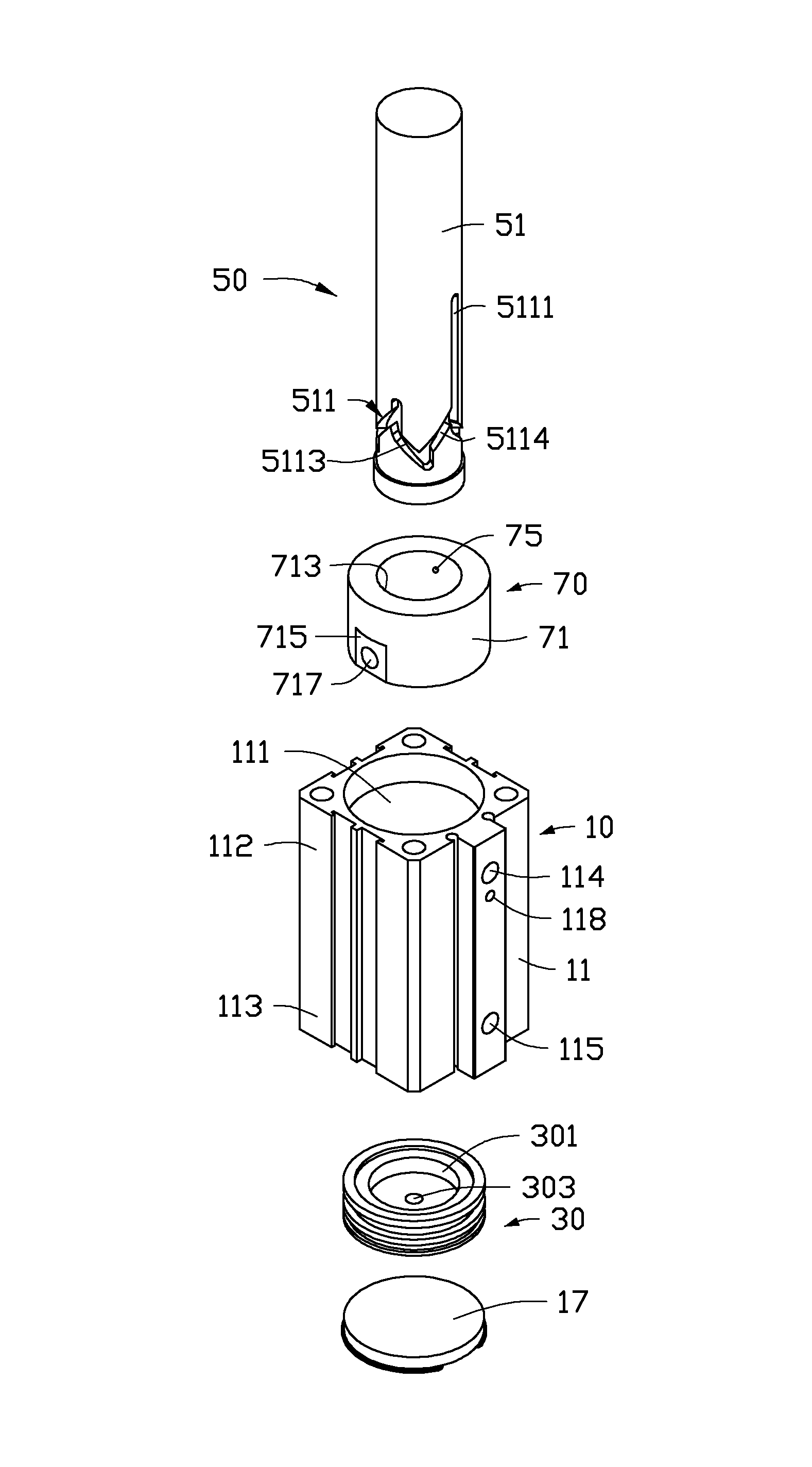
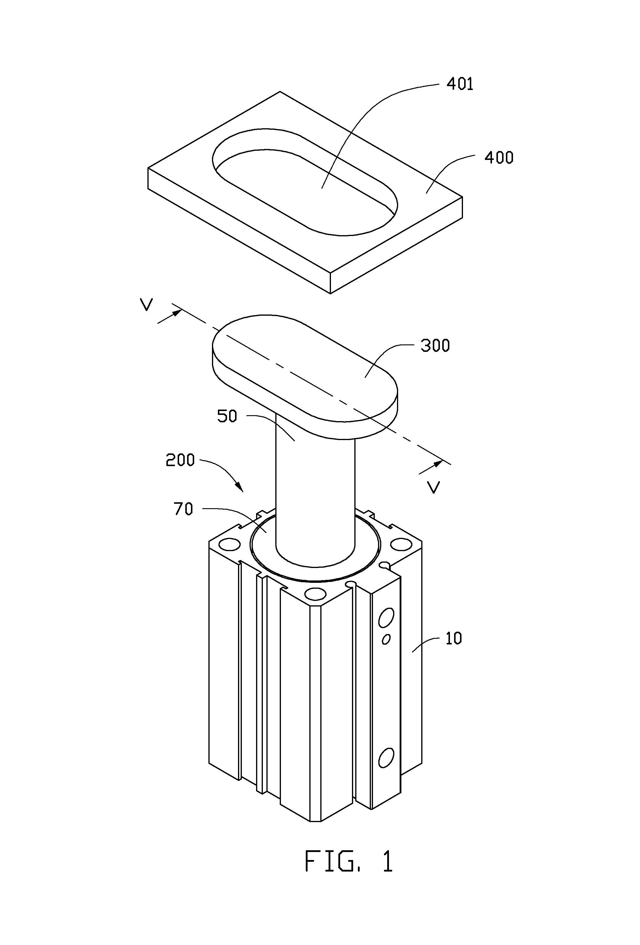
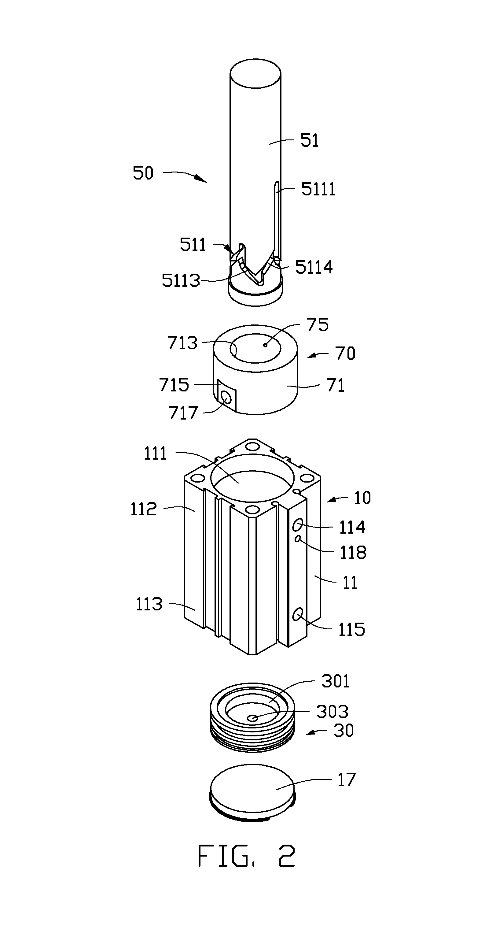
[0012]FIGS. 1, 2, and 5 show an embodiment of a rotating cylinder 200 with a press plate 300 and a support plate 400. The rotating cylinder 200 includes a main body 10, a piston head 30, a piston rod 50 and a guiding assembly 70. The guiding assembly 70 is fixedly received in the main body 10, the piston rod 50 passes through and engages with the guiding assembly 70. The piston head 30 is fixed to an end of the piston rod 50 and slidably received in the main body 10. The press plate 300 is fixed to an end of the piston rod 50 extending out of the main body 10. The support plate 400 is located above the rotating cylinder 200 and defines a through hole 401 for allowing the press plate 300 to pass therethrough. In the embodiment, the through hole 401 is substantially kidney shaped. The press plate 300 has a shape similar to the through hole 401 and a size less than the through hole 401. A workpiece (not shown) is located on the support plate 400, and the workpiece defines a hole of the...


PUM


Abstract

A rotating cylinder includes and a main body, a piston head, a piston rod and a guide assembly. The piston head slidably is received within the main body. The piston rod partially received within the main body, the piston head is fixed to the piston head, the piston rod defines one or more guiding groove adjacent to the piston head, the guiding groove includes a straight portion, a first helix portion and a second helix portion, the straight portion extends axially toward the piston head, the first helix portion curvedly extends away from the straight portion toward the piston head, the second helix portion curvedly extends from an end of the first helix portion toward a direction away from the piston head and the straight portion. The guide assembly is mounted on the main body and includes one or more guiding member slidably engaged with the guiding groove.

Description

BACKGROUND[0001]1. Technical Field[0002]The present disclosure relates to a cylinder, and more particularly, to a rotating cylinder.[0003]2. Description of Related Art[0004]A rotating cylinder is typically employed to clamp a workpiece in industrial usages. The rotating cylinder includes a piston rod defining a guide groove surrounding a periphery. A press plate may be dragged by the piston rod downward and be rotated about 90 degrees to clamp the workpiece on a support plate. When the workpiece has been machined, the press plate is pushed upward by the piston rod rotating backward about 90 degrees to release the workpiece. However, in the clamping process, the piston rod extends through the workpiece, at the same time the loading and offloading process of the workpiece on the support plate may interfere with the presence and movement of the piston rod, thus contact between the workpiece and the piston rod occurs quite easily, and this contact may result in damage to the appearance ...

Claims


Application Information

Patent Timeline
Patent Type & Authority Patents(United States)
IPC IPC(8): B23Q3/08B25B1/14B23Q3/06
CPCB23Q3/082B23Q3/069
Inventor CHOU, YU-CHENGWU, XIAO-FENG
Owner FU TAI HUA IND SHENZHEN
Learn More