Resin composition, optical layer, cover member, and moving body

a technology of optical layer and composition, applied in the direction of synthetic resin layered products, polyurea/polyurethane coatings, signalling/lighting devices, etc., can solve problems such as impaired appearan

Inactive Publication Date: 2020-11-19
SUMITOMO BAKELITE CO LTD
View PDF0 Cites 0 Cited by
  • Summary
  • Abstract
  • Description
  • Claims
  • Application Information

AI Technical Summary

Benefits of technology

[0024]The resin composition of the present invention is used for forming a second layer in an optical layer including a first layer and the second layer protecting the first layer, in which the first layer contains a resin material as a main material having light-transmitting properties and a visible light absorber which is dispersed in the resin material and absorbs visible light.
[0025]In the present invention, the resin composition contains a silicon-modified (meth) acryl resin, a urethane (meth) acrylate, and a polyfunctional (meth) acrylate. In a case where the second layer having an average thickness of 12 μm is formed on a base material containing a bisphenol-type polycarbonate-based resin as a main material, a coating film of a mixed solvent containing a petroleum-based solvent at a proportion equal to or higher than 45 wt % is formed on the second layer and left as it is under a condition of 85° C.×24 hours, the second layer is then returned to an atmosphere of 25° C., the mixed solvent is removed thereafter, and then a cross-cut method specified in JIS K 5600-5-6 is implemented on the second layer, an adherence of the second layer cut in the form of a lattice with respect to the base material is equal to or higher than 95%. Therefore, an optical layer including the second layer can be used as a cover member which is precisely inhibited or prevented from experiencing appearance impairment even though the second layer is exposed to chemicals such as a petroleum-based solvent. Accordingly, a moving body including the optical layer as a cover member is extremely reliable.

Problems solved by technology

In a case where the coating layer stained with the chemicals is left as it is, unfortunately, the appearance thereof is impaired.

Method used


Image

  • Resin composition, optical layer, cover member, and moving body
  • Resin composition, optical layer, cover member, and moving body
  • Resin composition, optical layer, cover member, and moving body

Examples


first embodiment

[0033]First, a first embodiment of the optical layer of the present invention will be described.

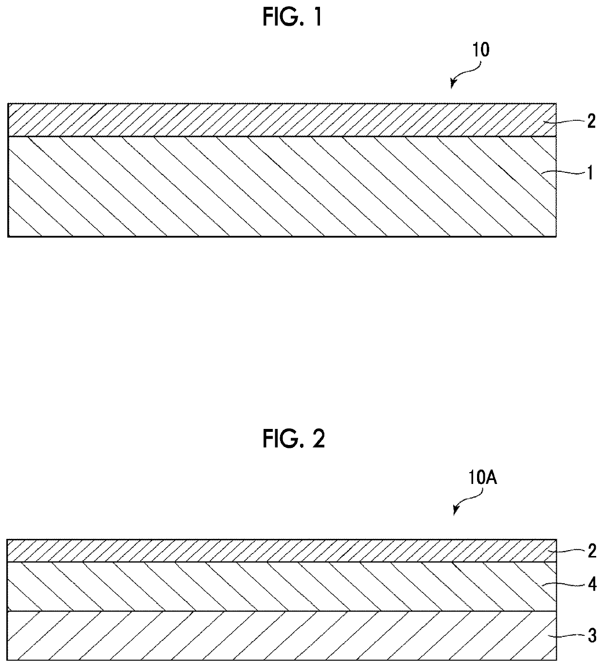
[0034]FIG. 1 is a vertical cross-sectional view illustrating the first embodiment of the optical layer of the present invention. Hereinafter, for the sake of description, the upper side and the lower side in FIG. 1 will be described as “top” and “bottom” respectively.

[0035]An optical layer 10 (optical film) is applied to a cover member. In the present embodiment, as shown in FIG. 1, the optical layer 10 has a base material layer 1 (first layer) and a protective layer 2 (second layer) which is laminated on the base material layer 1 and protects the base material layer 1.

[0036]In a case where the optical layer 10 is applied to a cover member, the optical layer 10 is installed such that the protective layer 2 faces outside and the base material layer 1 is on the side of a substance that is to be covered. In a case where the optical layer 10 is installed as described above, it is possible to ...

second embodiment

[0146]Next, a second embodiment of the optical layer of the present invention will be described.

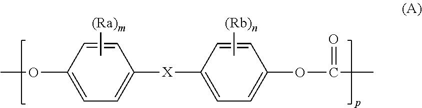
[0147]FIG. 2 is a vertical cross-sectional view illustrating the second embodiment of the optical layer of the present invention.

[0148]Hereinafter, an optical layer 10A of the second embodiment will be described. The description is focused on the differences with the optical layer 10 of the first embodiment, and the same matters as those of the optical layer 10 will not be described.

[0149]The optical layer 10 A of the present embodiment is the same as the first embodiment, except for the constitution of the base material layer.

[0150]In the present embodiment, the optical layer 10A has a visible light absorbing layer 3 which absorbs visible light, an ultraviolet absorbing layer 4 which absorbs ultraviolet rays, and the protective layer 2. The optical layer 10A is a laminate in which these layers are laminated in the above order from the lower side (see FIG. 2) . That is, in the present emb...

example 1

[0162][1] First, 99.62 wt % of a bisphenol A-type polycarbonate (manufactured by Mitsubishi Engineering-Plastics Corporation, “E2000”), 0.03 wt % of a first light absorber (quinoline; manufactured by Arimoto Chemical Co., Ltd., “plast yellow 8050”), 0.05 wt % of a second light absorber (anthraquinone A; manufactured by Arimoto Chemical Co., Ltd., “Plast blue 8590”), 0.05 wt % of a second light absorber (anthraquinone B; manufactured by Arimoto Chemical Co., Ltd., “SDO-7”), 0.07 wt % of a third light absorber (perinone; manufactured by Arimoto Chemical Co. , Ltd., “Plast red 8370”), and 0.18 wt % of a fourth light absorber (UVA; manufactured by ADEKA CORPORATION, “LA-31G”) were stirred-mixed together, thereby preparing a resin composition for forming a base material layer.

[0163]A mixture (manufactured by DIC Corporation, WMZ-306) of 10.5 wt % of a silicon-modified (meth) acryl resin and an acrylate monomer as a silicon-modified (meth) acryl resin, 16.8 wt % of alicyclic difunctional ...


PUM

PropertyMeasurementUnit
thicknessaaaaaaaaaa
thicknessaaaaaaaaaa
transmittanceaaaaaaaaaa

Abstract

A resin composition of the present invention is used for forming a second layer in an optical layer 10, contains a silicon-modified (meth) acryl resin, a urethane (meth) acrylate, and a polyfunctional (meth) acrylate, and satisfies the following condition A, in which the optical layer 10 includes a first layer (base material layer 1) containing a resin material and a visible light absorber and the second layer (protective layer 2) protecting the first layer.Condition A: In a case where the second layer is formed on a base material, a coating film of a mixed solvent containing a petroleum-based solvent at a proportion equal to or higher than 45 wt % is formed on the second layer and left as it is, and then the mixed solvent is removed, an adherence, which is determined by a cross-cut method, of the second layer cut in the form of a lattice with respect to the base material is equal to or higher than 95%.

Description

TECHNICAL FIELD[0001]The present invention relates to a resin composition used for forming an optical layer, an optical layer, a cover member, and a moving body.BACKGROUND ART[0002]Generally, molded articles formed of a resin material having light-transmitting properties are light and have excellent molding properties. Particularly, the molded articles formed of a polycarbonate-based resin have excellent transparency and higher impact resistance compared to glass products. Therefore, these are frequently used in covers and windshield boards for various lamp lenses, window materials, instruments, and the like (for example, see PTL 1).[0003]Such molded articles can be used as a cover member that moving bodies such as automobiles or two-wheel vehicles have. These moving bodies are used outdoors. Accordingly, in the moving bodies, a cover member including a hardcoat layer (coating layer) is used which is formed by performing a hard coating treatment on the surface of a molded article su...

Claims


Application Information

Patent Timeline
Patent Type & Authority Applications(United States)
IPC IPC(8): B32B7/023C08F290/06C08L75/14C08L33/12B32B27/30B32B27/36
CPCC08L75/14B32B27/30C08L2203/16C08L33/12B32B27/36B32B7/023C08F290/068C09D133/08C09D175/14C09D143/04C08F222/104C08G18/61C08G18/6295C09D175/04C09D4/06C08J7/046F21S43/26G02B1/14C08F290/067C09D151/08C08J7/0427C08J2369/00C08J2433/04G02B5/208G02B5/223C08F222/1065C08F230/08C08F222/1025
Inventor FUNAKOSHI, YUICHIRO
Owner SUMITOMO BAKELITE CO LTD
Why Eureka
Try Eureka