
Method and device for the impact treatment of transition radii of a crankshaft

a technology of transition radii and impact treatment, which is applied in the direction of heat treatment furnaces, heat treatment apparatus, furnaces, etc., can solve the problems of increasing the load of modern engines, affecting the performance of modern engines, and requiring complex components such as clutches and/or spring systems, so as to improve the fatigue strength, and improve the effect of fatigue strength

Active Publication Date: 2021-05-20
MASCHFAB ALFING KESSLER
View PDF0 Cites 0 Cited by
  • Summary
  • Abstract
  • Description
  • Claims
  • Application Information

AI Technical Summary

Benefits of technology

The patent text discusses the effectiveness of strengthening the crankshaft of a machine to prevent failure under high loads. It explains that while it is important to have the same types of internal pressure in the heavily loaded areas, it is not necessary in the areas where the machine is not under high pressure. The text also mentions that fully encircling the crankshaft with impact hardening is a costly solution. However, the text shows that targeted strengthening of the transition radius can increase the fatigue strength of the machine by up to 5%.

Problems solved by technology

Owing to the continuously progressing development and increasing performance of internal combustion engines and stringent emissions requirements placed on these, modern engines are consequently subjected to ever greater loading.
For this purpose, however, complex components such as for example transmissions, clutches and / or spring systems are required within the drive device in order to prevent the drive device from being damaged by the “forced stops”.
Here, the mechanical components required to ensure a robust installation are complex and expensive.

Method used


Image

  • Method and device for the impact treatment of transition radii of a crankshaft
  • Method and device for the impact treatment of transition radii of a crankshaft
  • Method and device for the impact treatment of transition radii of a crankshaft

Examples


Embodiment Construction

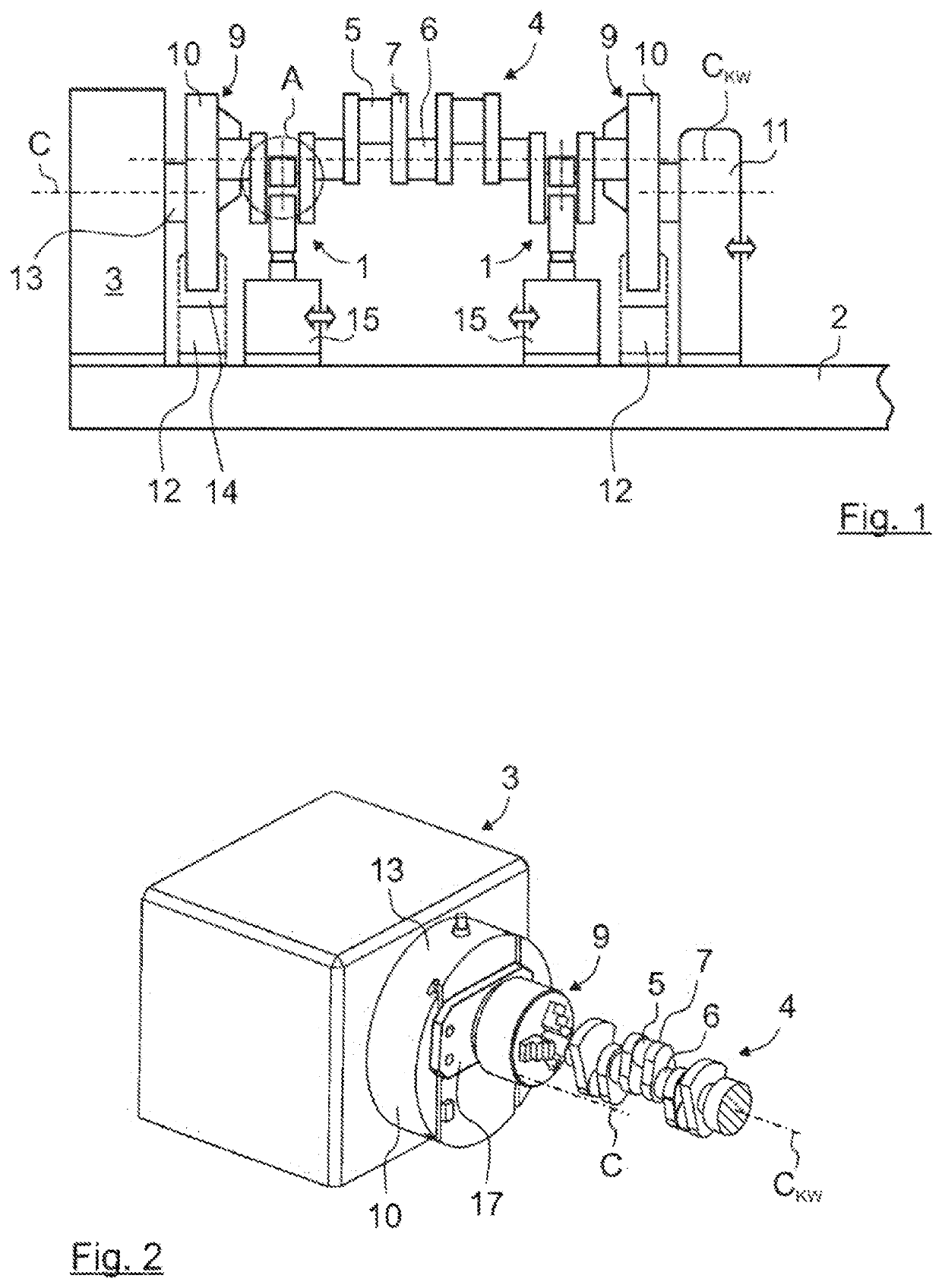
[0208]The apparatus illustrated in an overall view in FIG. 1 basically corresponds in terms of its construction to the apparatuses as per DE 34 38 742 C2 and EP 1 716 260 B1 with one or more impact devices 1, for which reason only the important parts, and the differences in relation to the prior art, will be discussed in more detail below.

[0209]The apparatus has a machine bed 2 and a drive device 3. The drive device 3 is used to move or rotate a crankshaft 4 along a direction of rotation into an impact position.

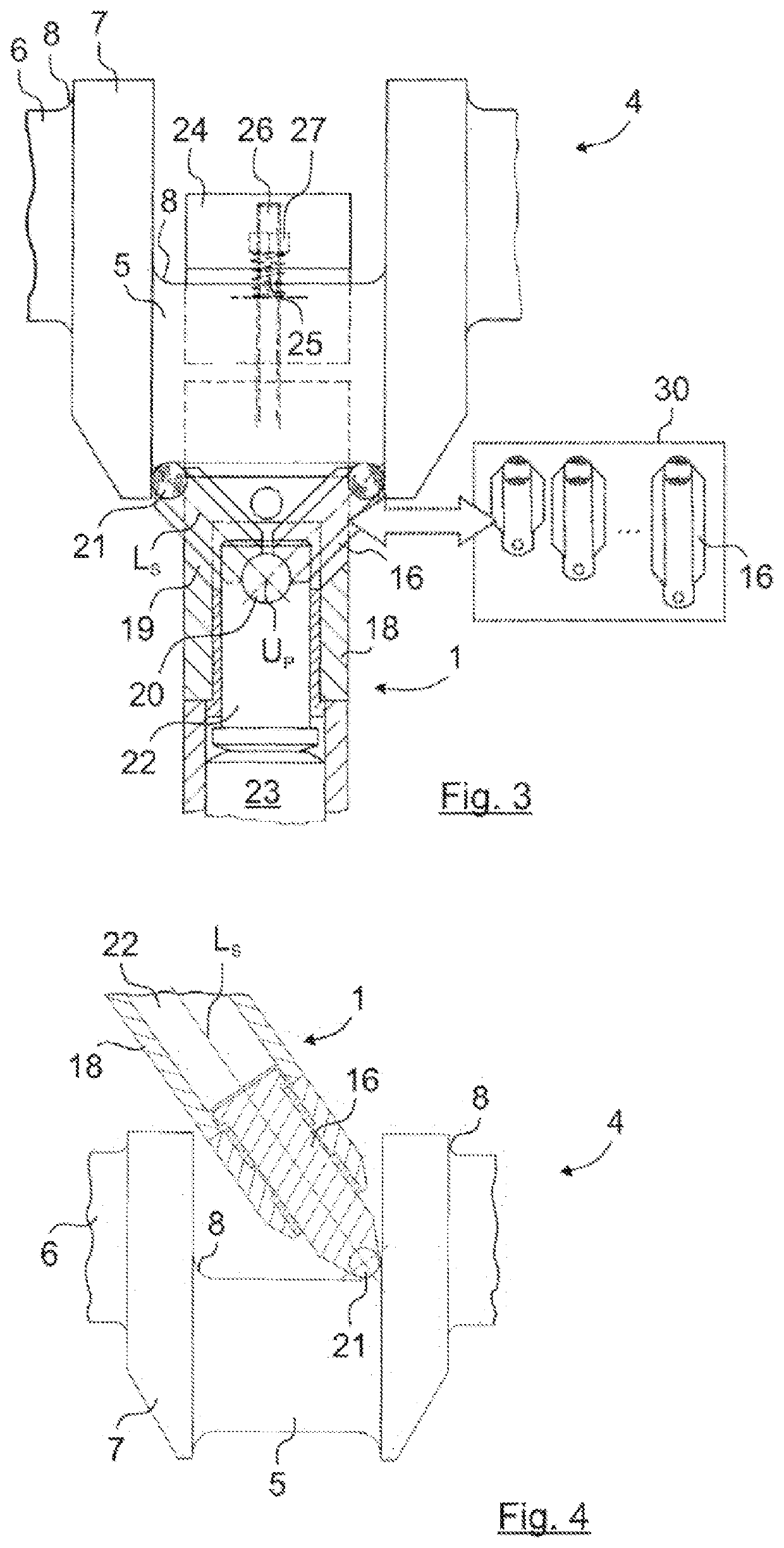
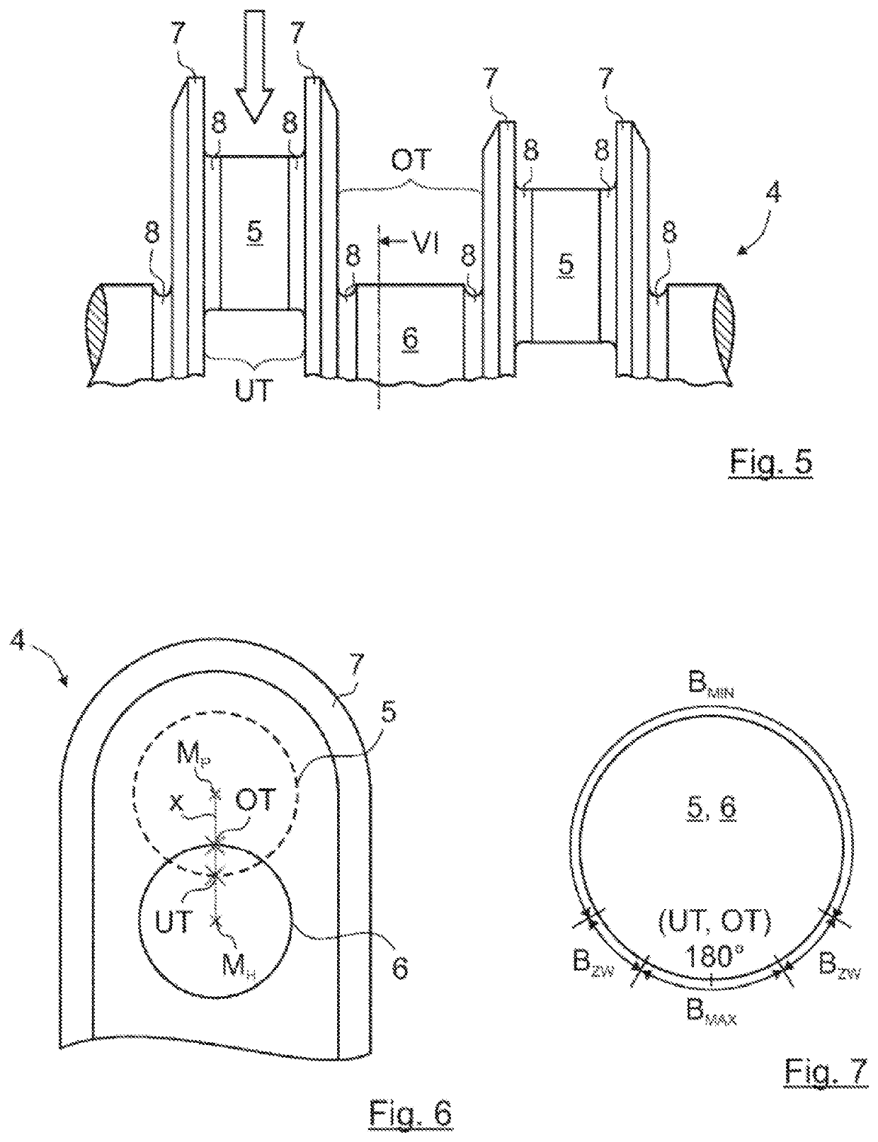
[0210]The crankshaft 4 has connecting-rod bearing journals 5 and main bearing journals 6, between which crank webs 7 are arranged in each case. Transition radii 8 (see FIGS. 3 to 5 and 13 to 18) are formed between connecting-rod bearing journals 5 and crank webs 7 and between main bearing journals 6 and crank webs 7, or generally between transitions in cross section of the crankshaft 4.

[0211]At that side of the crankshaft 4 which faces toward the drive device 3, there is prov...


PUM

PropertyMeasurementUnit
diametersaaaaaaaaaa
lengthaaaaaaaaaa
diametersaaaaaaaaaa

Abstract

The invention relates to a method for the impact treatment of transition radii (8) of a crankshaft (4), in particular transition radii (8) between connecting rod bearing journals (5) and crank webs (7) and / or transition radii (8) between main bearing journals (6) and the crank webs (7) of the crankshaft (4). In order to apply an impact force (FS) to at least one of the transition radii (8) along the respective transition radius (8) circulating about the crankshaft (4) in an annular manner, a heavily loaded region (BMAX), a lightly loaded region (BMIN), and intermediate regions (BZW) lying therebetween are defined, and an impact treatment is then carried out such that the impact force (FS) introduced into the intermediate regions (BZW) is increased in the direction of the heavily loaded region (BMAX).

Description

BACKGROUND OF THE INVENTION[0001]The invention relates to a method for the impact hardening of transition radii of a crankshaft, in particular of transition radii between connecting-rod bearing journals and crank webs and / or transition radii between main bearing journals and the crank webs of the crankshaft, as per the preamble of claim 1.[0002]The invention also relates to an apparatus for carrying out the method for the impact hardening of transition radii of a crankshaft.[0003]The invention also relates to a crankshaft.[0004]Owing to the continuously progressing development and increasing performance of internal combustion engines and stringent emissions requirements placed on these, modern engines are consequently subjected to ever greater loading. For this reason, the motor industry places high demands with regard to strength inter alia on the crankshaft, which is subjected to high loading and which is important for the function of an internal combustion engine. Here, in terms ...

Claims


Application Information

Patent Timeline
Patent Type & Authority Applications(United States)
IPC IPC(8): B23P9/04
CPCB23P9/04B23P2700/07C21D7/04C21D9/30
Inventor REEB, ALFONSSCHMIDT, JOCHENGRIMM, KONRAD
Owner MASCHFAB ALFING KESSLER
Learn More