Arc welding machine adapted for remote controlled current adjustment

a technology of remote control and arc welding, applied in the field of welding, can solve the problems of time and effort, slow the progress of arc welding, etc., and achieve the effect of convenient and convenient depressing the fob

Active Publication Date: 2015-05-19
SCHMIDT DOUG
View PDF24 Cites 2 Cited by
  • Summary
  • Abstract
  • Description
  • Claims
  • Application Information

AI Technical Summary

Benefits of technology

[0013]In a preferred embodiment of the instant invention, the remote switching means configure the transmitter component as a small fob type remote control, which is tactily actuatable. The fob remote control preferably has two actuation buttons, a current enhancement function button and a current suppression function button. In the instant invention, the switching means preferably ergonomically incorporate and include a welder's helmet, and the preferred fob type remote control is conveniently and ergonomically attached to the helmet at an inner neckline surface.
[0014]In operation of the instant invention, and assuming a provision of preferred components and arrangements of components as described above, a welder may, during an ongoing process of arc welding and without any significant welding interruption, raise a hand to the lower neckline edge of his or her welding helmet. Such welder may reach fingers therein to the remote control fob component attached at that interior location. Thereafter, the welder may easily and conveniently depress the fob's “current up” adjustment button or the fob's “current down” adjustment button. In the preferred embodiment, pressing either of such buttons transmits a discreet signal to the receiver, which pulse actuates the reversible DC electric motor. In response, the motor turns a short and preferably calibrated angular distance. Such short motor actuating pulse advantageously produces small incremental adjustments of arc welding amperage.

Problems solved by technology

In performing such steps incident to increasing or decreasing the current within an arc welding circuit, such welder often is undesirably required to interrupt ongoing welding and walk to and from the welding machine, in order to directly manipulate the machine's current adjustment controls.
Mechanically imposed requirements for performing such current adjustment steps undesirably waste time and effort, and undesirably slow the progress of arc welding.

Method used


Image

  • Arc welding machine adapted for remote controlled current adjustment
  • Arc welding machine adapted for remote controlled current adjustment
  • Arc welding machine adapted for remote controlled current adjustment

Examples


Embodiment Construction

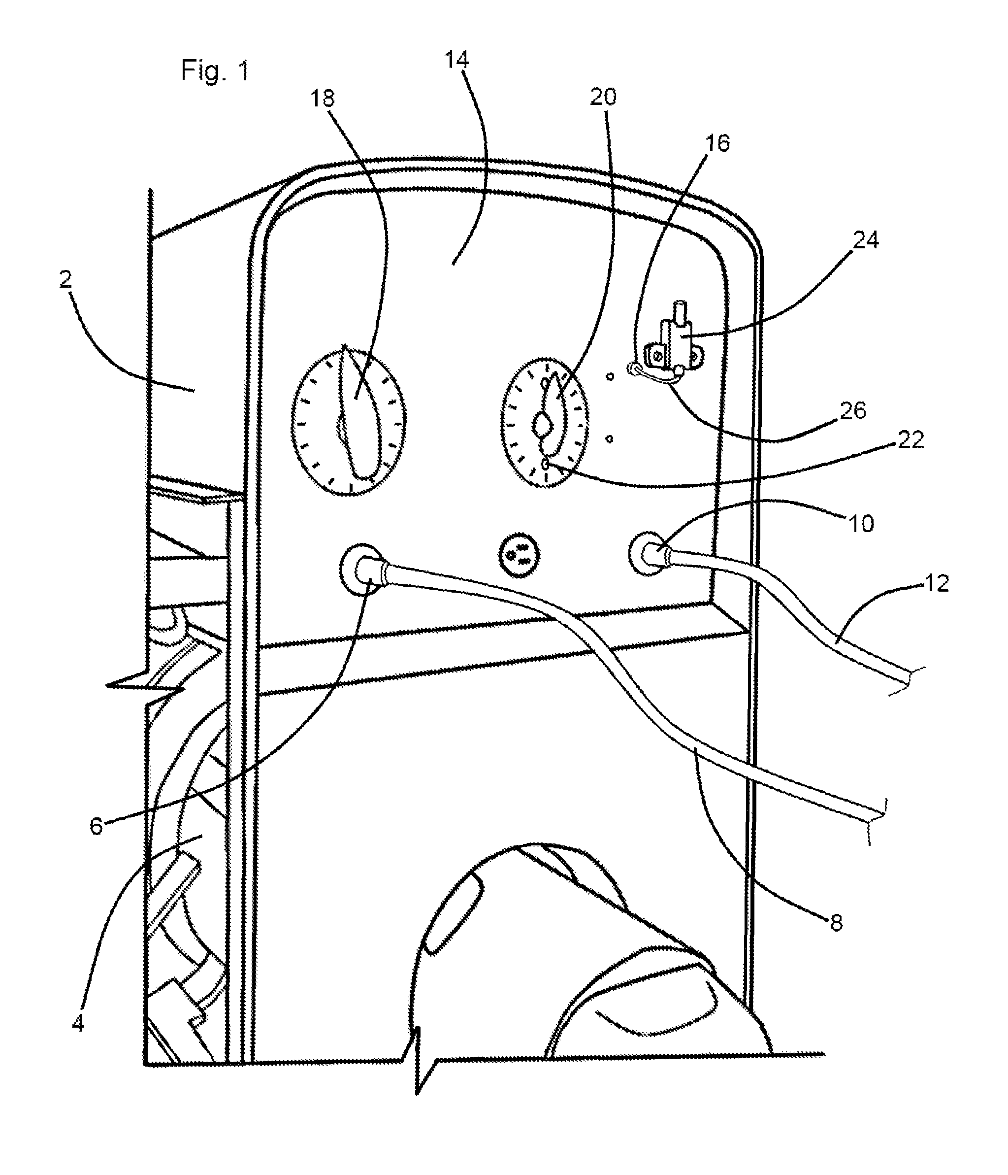
[0022]Referring now to the drawings and in particular to Drawing FIG. 1, the instant inventive arc welding assembly preferably comprises a durable metal equipment case 2, such case commonly protectively housing internal combustion motor and electrical generator components 4. The case 2 preferably has a forward control panel plate 14, such plate 14 conventionally supporting and having mounted thereto a gross welding amperage or current control 18, a fine current control 20, a ground or negative electrode terminal 6, an attached ground cable 8, and a positive electrode terminal 10 with attached cable 12. An electrode holder and welding stick or arc welding rod combination (not depicted within views) is typically attached to the distal end of cable 12 for use in arc welding of metal work pieces.

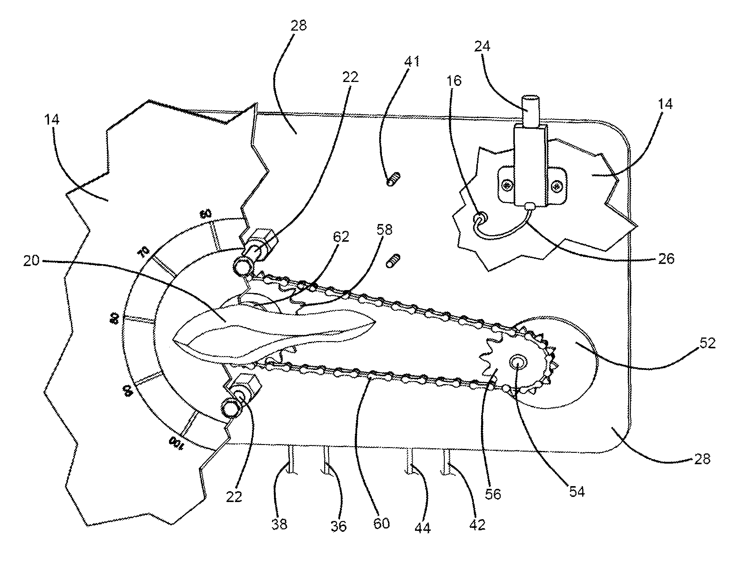
[0023]Referring simultaneously to FIGS. 4 and 5, a mounting plate 28 is provided, such plate preferably being interconnected with the control panel plate 14 by first mounting means. In a preferr...


PUM

PropertyMeasurementUnit
poweraaaaaaaaaa
reversing polarityaaaaaaaaaa
currentaaaaaaaaaa

Abstract

An arc welding assembling including a case having a control panel plate having a plurality of apertures, and having front and rear sides; a mounting plate; a plurality of mounting posts interconnecting the control panel plate and the mounting plate, and positioning the mounting plate rearwardly from the control panel plate to define a drive linkage space; a rheostat having an axle and being supported upon the mounting plate, the rheostat's axle extending forwardly through the drive linkage space and protruding from one of the control panel plate's apertures; a turn handle attached to the rheostat axle's forward end; an electric motor supported upon the mounting plate, and having a rotary output within the drive linkage space; a power transfer assembly within the drive linkage space for translating rotary power from the electric motor to the rheostat's axle; and a remote switching transmitter and radio receiver combination connected operatively to the electric motor.

Description

FIELD OF THE INVENTION[0001]This invention relates to welding. More particularly, this invention relates to arc welding machines and electro-mechanical equipment and components associated with arc welding machines.BACKGROUND OF THE INVENTION[0002]Welders who perform arc welding through the use of arc welding machines or rigs commonly have a need of performing fine tuning or precising adjustment of the electrical current or amperage within the arc welding electrical circuit. Where molten metal temperatures between a stick welding or arc welding rod and a metal work piece become excessive, the welder may desirably effect a current reducing adjustment through actuation of current adjusting controls which are typically presented upon the arc welding machine's control panel. Alternatively, where such molten metal temperatures are deficient, current may similarly be increased.[0003]In performing such steps incident to increasing or decreasing the current within an arc welding circuit, suc...

Claims


Application Information

Patent Timeline
Patent Type & Authority Patents(United States)
IPC IPC(8): B23K9/10
CPCB23K9/10B23K9/1087
Inventor SCHMIDT, DOUG
Owner SCHMIDT DOUG
Why Eureka
Try Eureka