Dual-diaphragm acoustic transducer

a dual-diaphragm, acoustic transducer technology, applied in the direction of deaf-aid sets, plane diaphragms, electrical devices, etc., can solve the problems of lowering sensitivity, and achieve the effect of improving sensitivity and enhanced sound pressure sensing rang

Inactive Publication Date: 2015-05-19
MERRY ELECTRONICS (SHENZHEN) CO LTD
View PDF2 Cites 9 Cited by
  • Summary
  • Abstract
  • Description
  • Claims
  • Application Information

AI Technical Summary

Benefits of technology

[0006]The present invention has been accomplished under the circumstances in view. It is the main object of the present invention to provide a dual-diaphragm acoustic transducer, which enhances the sound pressure sensing range and improves the sensitivity without increasing the sensing area.
[0008]Preferably, the support unit further comprises a supporting base affixed to the substrate. The supporting base is provided for the connection of the outer diaphragm directly or by means of at least two symmetrical elastic supporting members, thereby rendering a support effect.
[0010]Thus, subject to the arrangement of the inner and outer diaphragms and the connection of the multiple elastic supporting members, the dual-diaphragm acoustic transducer enables the inner diaphragm to have a relatively larger amount of vertical displacement than the outer diaphragm when the inner and outer diaphragms are simultaneously forced by a sound wave pressure, thereby enhancing the sensitivity when the sensing area remains unchanged.

Problems solved by technology

However, this design adopts one single sensing device (one single diaphragm), and this single sensing device may be unable to sense a very small volume of sound, lowering the sensitivity.
However, increasing the sensing area will affect the arrangement of the configuration of the whole structure.

Method used


Image

  • Dual-diaphragm acoustic transducer
  • Dual-diaphragm acoustic transducer
  • Dual-diaphragm acoustic transducer

Examples


Embodiment Construction

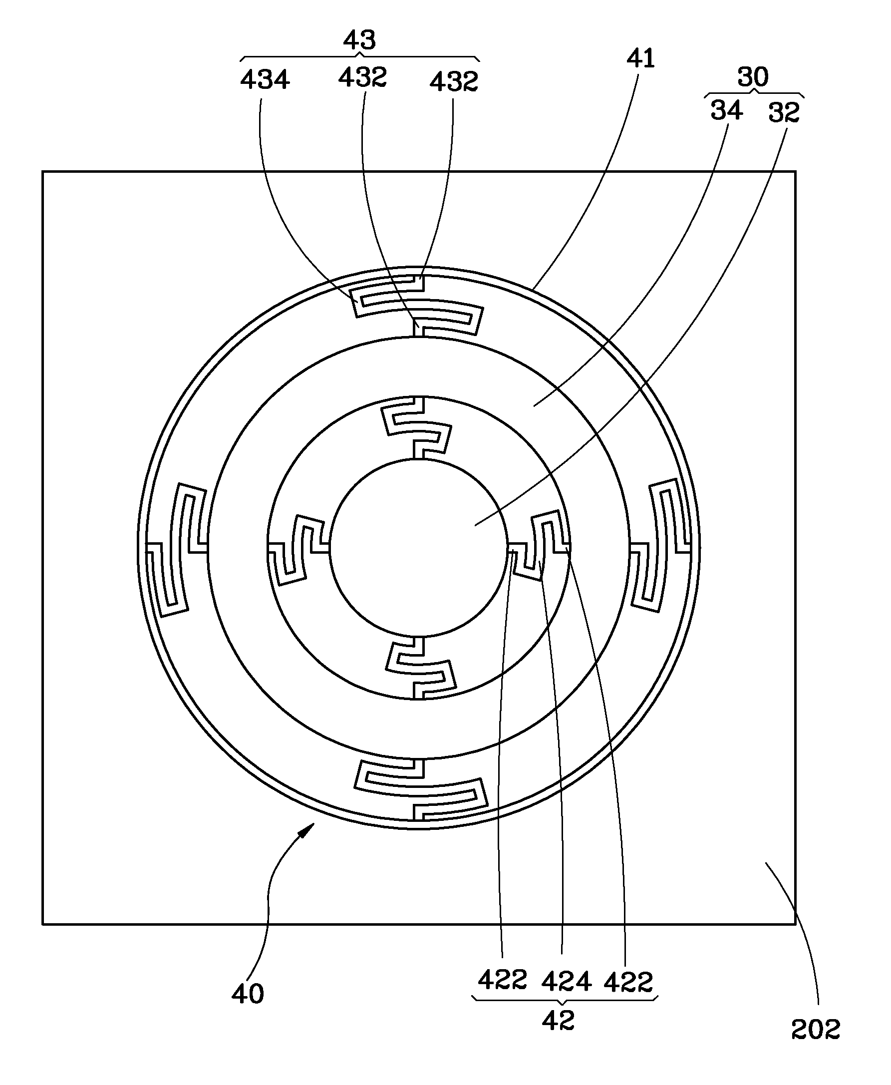
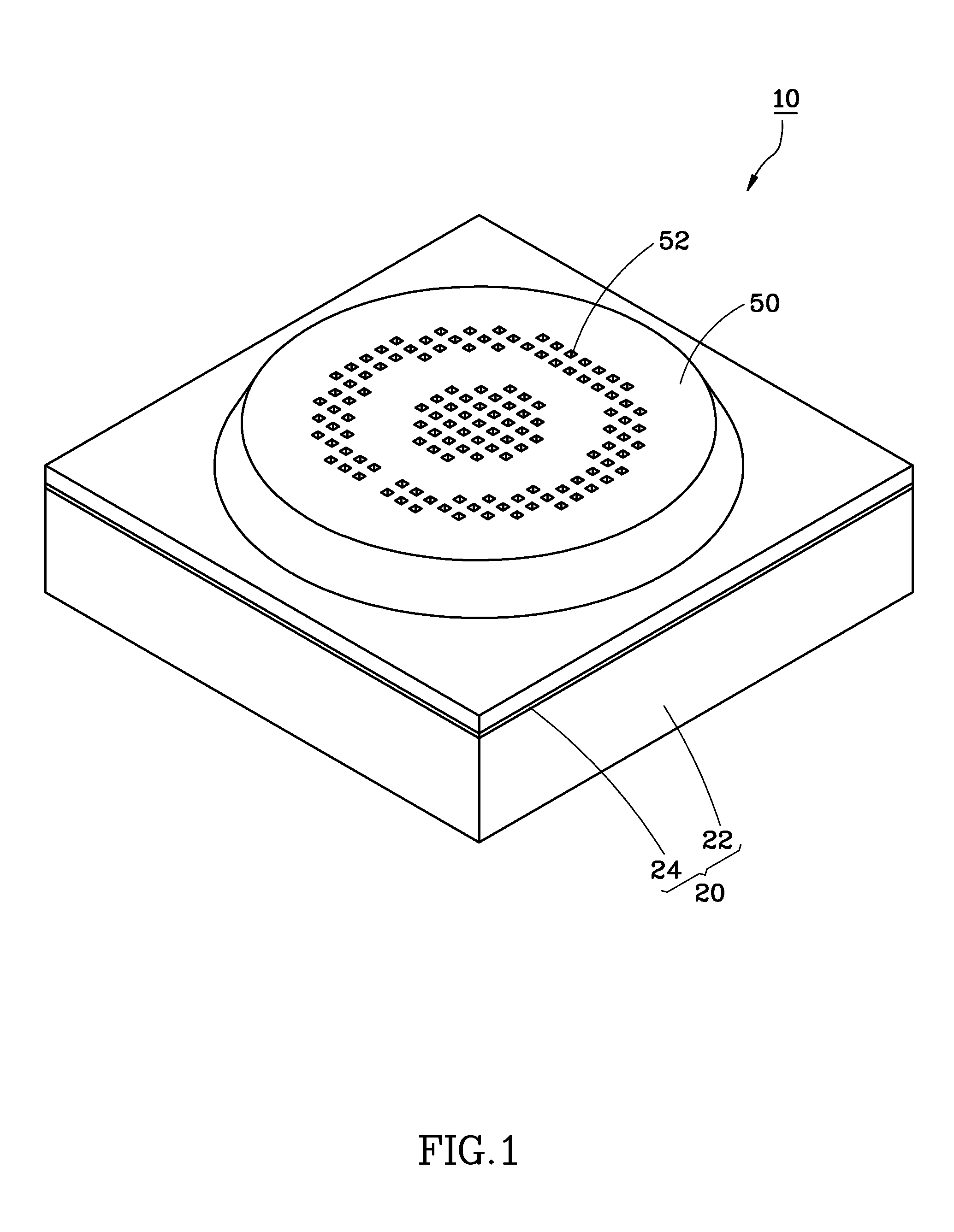
[0018]Referring to FIGS. 1-3, a dual-diaphragm acoustic transducer 10 in accordance with a first embodiment of the present invention is shown. The dual-diaphragm acoustic transducer 10 comprises a substrate 20, a sound wave sensing unit 30, and a support unit 40.

[0019]Referring also to FIG. 4, the substrate 20 comprises a silicon layer 22, and an insulating layer 24 covered on the top surface of the silicon layer 22. Thus, the top surface of the insulating layer 24 and the bottom surface of the silicon layer 22 are respectively defined as opposing first side 202 and second side 204 of the substrate 20. Further, the substrate 20 comprises an opening 26 cut through the first side 202 and the second side 204 for the passing of sound waves.

[0020]As shown in FIG. 3 and FIG. 4, the sound wave sensing unit 30 is mounted at the first side 202 of the substrate 20 corresponding to the opening 26, comprising an inner diaphragm 32 and an outer diaphragm 34 extending around the inner diaphragm 3...


PUM


Abstract

A dual-diaphragm acoustic transducer includes a substrate defining an opening, an inner diaphragm and an outer diaphragm concentrically mounted at one same side of the substrate corresponding to the opening of the substrate, and a plurality of elastic supporting members connected between the outer perimeter of the inner diaphragm and the inner perimeter of the outer diaphragm. Thus, when a sound wave enters the opening of the substrate, the sound wave pressure forces the outer diaphragm to displace and to carry the inner diaphragm to move, and the inner diaphragm itself will also be forced by the sound wave pressure to have a larger displacement than the outer diaphragm, enhancing the sensitivity. Further, using the inner and outer diaphragms to respond to different sound wave pressures can enhance the sound wave pressure sensing range.

Description

BACKGROUND OF THE INVENTION[0001]1. Field of the Invention[0002]The present invention relates to acoustic transducer technology, and more particularly to a dual-diaphragm acoustic transducer for converting sound waves to electrical signals.[0003]2. Description of the Related Art[0004]With the rapid development of the 4C electronics (computer, communication, consumer electronics and car industries), mobile communication products such as smart phone, Bluetooth headset and microphone have become one of the mainstreams. Due to the demand for higher tone quality of mobile communication products is increasing, an acoustic transducer for use in the aforesaid mobile communication products must have good sensitivity.[0005]A relevant prior art acoustic transducer, for example, U.S. Pat. No. 8,104,354 discloses a capacitance sensor that comprises a substrate, a sensing device, a movable frame, a first electrode and a second electrode respectively mounted at the substrate corresponding to the s...

Claims


Application Information

Patent Timeline
Patent Type & Authority Patents(United States)
IPC IPC(8): H04R25/00H04R7/16
CPCH04R7/16H04R7/06H04R7/20H04R19/005
Inventor CHEN, JEN-YICHANG, CHAO-SENWANG, CHUN-CHIEHCHANG, YONG-SHIANG
Owner MERRY ELECTRONICS (SHENZHEN) CO LTD
Why Eureka
Try Eureka