
Road surface slope estimating device

a technology for estimating devices and roads, applied in vehicle position/course/altitude control, process and machine control, instruments, etc., can solve problems such as large estimation errors, improve traceability, and improve the effect of noise immunity and responsiveness

Active Publication Date: 2015-05-19
NISSAN MOTOR CO LTD
View PDF2 Cites 2 Cited by
  • Summary
  • Abstract
  • Description
  • Claims
  • Application Information

AI Technical Summary

Benefits of technology

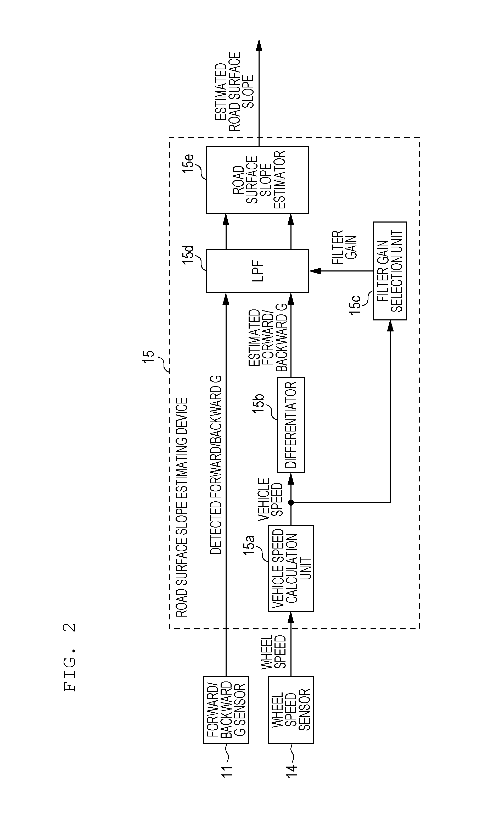
The present invention is a device that can estimate the slope of a road surface with both high noise immunity and responsiveness to changes in the slope. The device uses a filtering unit with changing filter characteristics based on the rate of change of the road surface slope. This results in improved tracking of the road surface slope when it is changing quickly and reduced noise when the slope is changing slowly. Overall, the device achieves both noise immunity and responsiveness to changes in road surface slope.

Problems solved by technology

In the technology of the related art described above, since the intensity of the filter is constant with respect to a change in road surface slope, the traceability of an estimated road surface slope to an actual change in road surface slope deteriorates as the rate of change of the road surface slope increases, resulting in a large estimation error.

Method used


Image

  • Road surface slope estimating device
  • Road surface slope estimating device
  • Road surface slope estimating device

Examples


Embodiment Construction

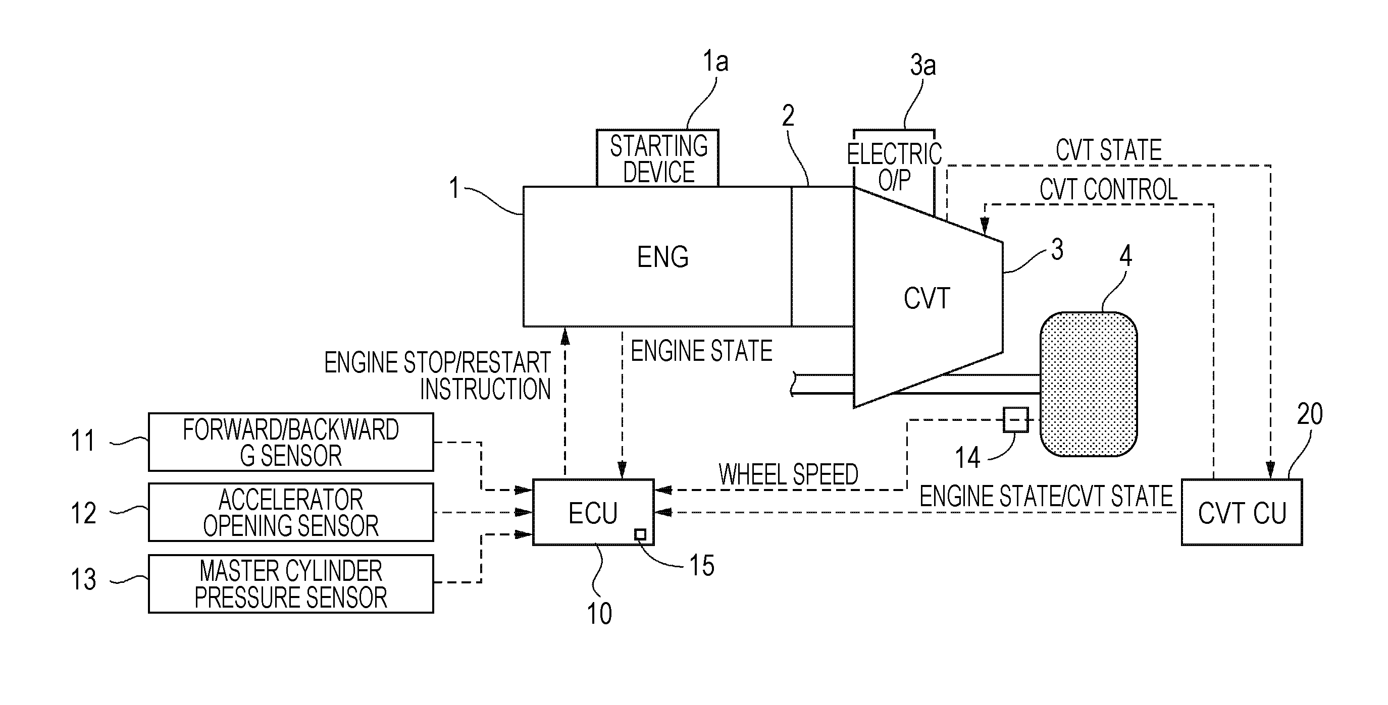
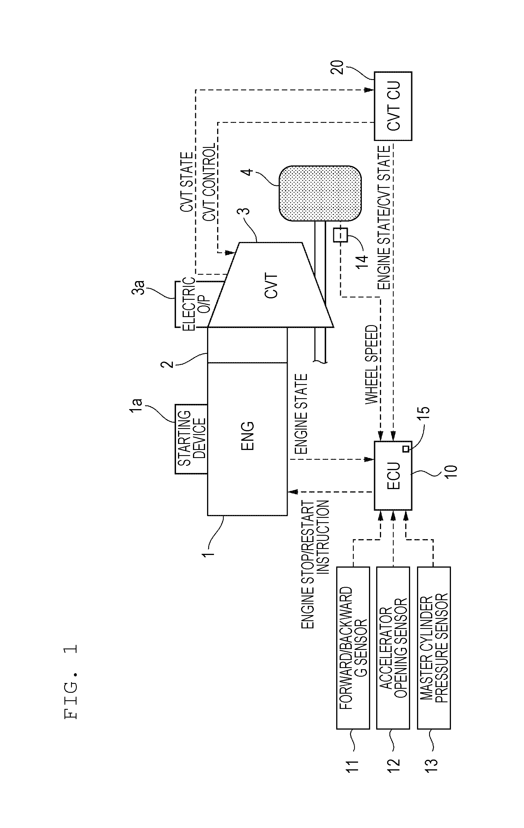
[0017]A road surface slope estimating device according to embodiments of the present invention will be described hereinafter with reference to the drawings.

[0018]First, a configuration according to a first embodiment will be described.

[0019]FIG. 1 is a system diagram illustrating an engine automatic stop control apparatus according to the first embodiment. A rotational drive force input from an engine 1 is input to a belt continuously variable transmission (CVT) 3 through a torque converter 2, and is transmitted to drive wheels 4 after the speed of the rotational drive force has been changed with a desired transmission gear ratio.

[0020]The engine 1 includes a starting device 1a that initiates an engine start process. Specifically, the engine 1 is equipped with a starter motor, with which engine cranking is performed in accordance with an engine start instruction and fuel is injected into the engine 1. When the engine 1 becomes rotating in a self-sustaining manner, the starter motor ...


PUM


Abstract

A road surface slope estimating device changes filter characteristics of a filter with respect to a detected vehicle body attitude value in accordance with an actual rate of change of road surface slope so as to enhance the filter characteristics when the rate of change of the road surface slope is low and to degrade the filter characteristics when the rate of change of the road surface slope is high.

Description

TECHNICAL FIELD[0001]The present invention relates to a road surface slope estimating device.BACKGROUND[0002]Japanese Unexamined Patent Application Publication No. 2009-040308 discloses a technology for, when estimating a road surface slope using a value detected by an acceleration sensor and a differentiated value of a vehicle speed determined by a wheel speed sensor, removing by using a low-pass filter noise components caused by changes in the attitude (squat, dive, shift shock) of a vehicle body or input disturbances of a road surface (such as irregularities).[0003]In the technology of the related art described above, since the intensity of the filter is constant with respect to a change in road surface slope, the traceability of an estimated road surface slope to an actual change in road surface slope deteriorates as the rate of change of the road surface slope increases, resulting in a large estimation error.BRIEF SUMMARY[0004]The present invention provides a road surface slope...

Claims


Application Information

Patent Timeline
Patent Type & Authority Patents(United States)
IPC IPC(8): G06F17/00B60W40/076B60W50/00
CPCG06F17/00B60W40/076B60W2050/0052B60W2520/10B60W2520/105
Inventor MATSUDA, TAKASHI
Owner NISSAN MOTOR CO LTD
Learn More