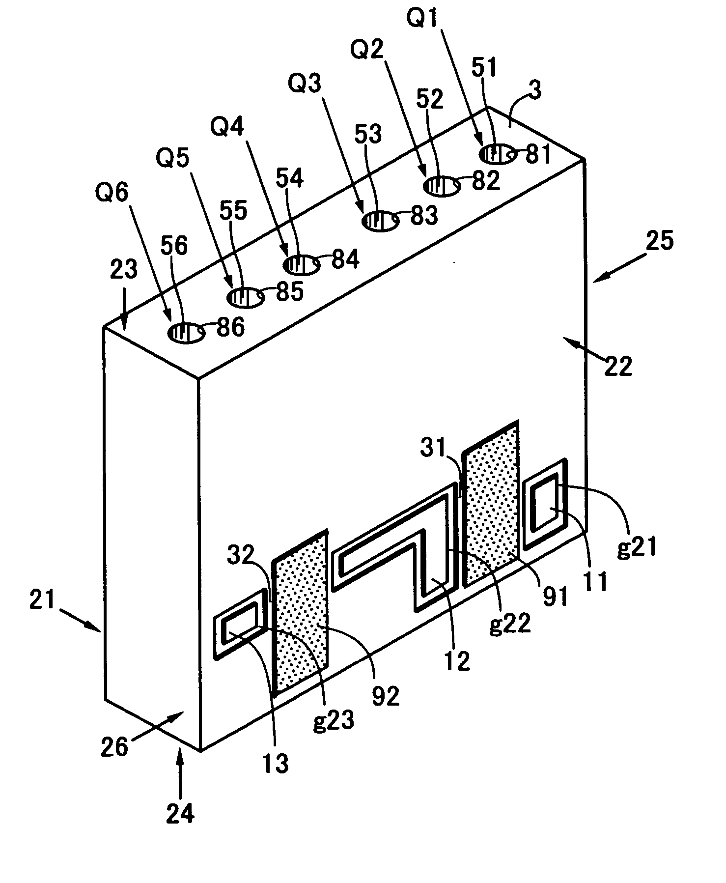
Dielectric device
a technology of dielectric devices and filters, applied in the direction of electrical equipment, multiple-port networks, waveguides, etc., can solve the problems of filter characteristics, failure to disclose a means, and fluctuation of pass band width, so as to improve filter characteristics such as the pass band width
- Summary
- Abstract
- Description
- Claims
- Application Information
AI Technical Summary
Benefits of technology
Problems solved by technology
Method used
Image
Examples
first embodiment
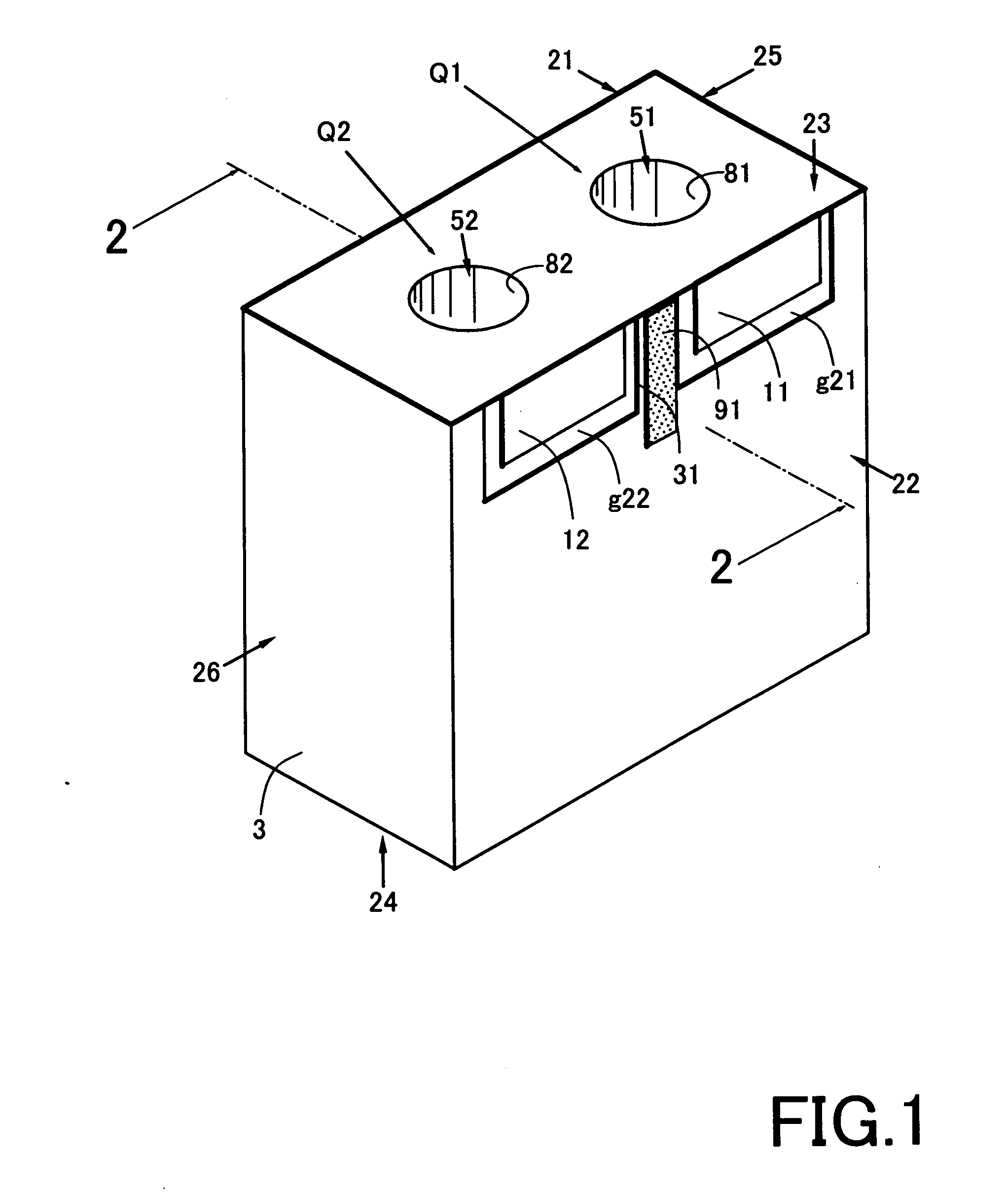
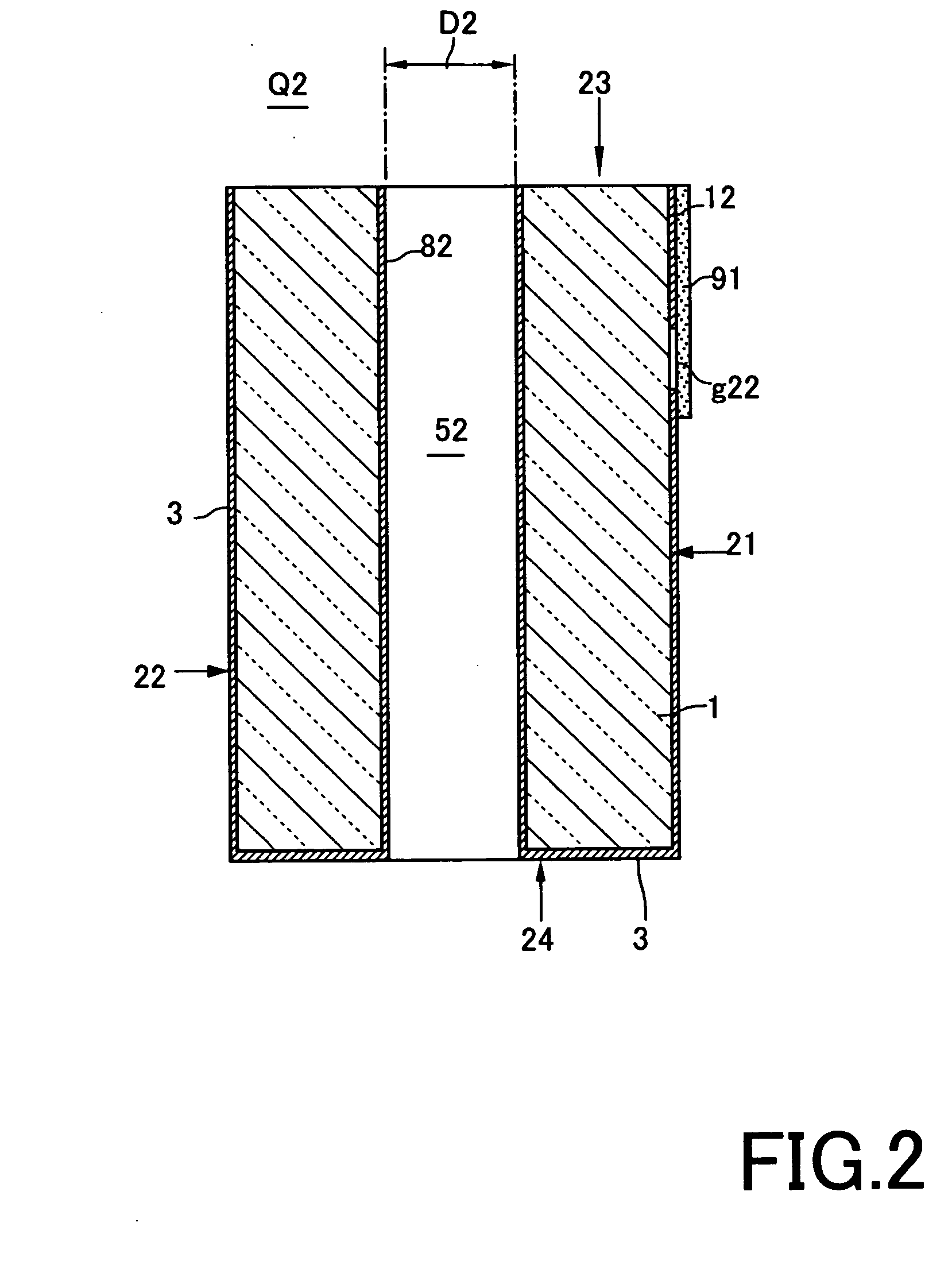
[0056] Referring to FIGS. 1 and 2, a dielectric device according to the present invention includes a dielectric substrate 1 and two resonator units Q1, Q2. The dielectric substrate 1 is formed from a well-known dielectric ceramic to have a generally hexahedral shape with first to sixth external surfaces 21 to 26. Typically, an external conductor film 3 may be formed by baking, plating or the like to contain copper, silver or the like as a main component.
[0057] The resonator unit Q1 includes a hole 51. The hole 51 opens on the third and fourth surfaces 23, 24 with an internal conductor 81 therein. The internal conductor 81 connects with the external conductor film 3 at one end opening on the fourth external surface 24. Alternatively, the internal conductor 81 may be formed by filling a part or the whole of the hole 51.
[0058] The resonator unit Q2, which has substantially the same configuration as the resonator unit Q1, includes a hole 52. Since the resonator unit Q2 has the same con...
second embodiment
[0062] Referring to FIGS. 3 to 6, a dielectric device according to the present invention includes a dielectric substrate 1 and two resonator units Q1, Q2. The dielectric substrate 1 is formed from a well-known dielectric ceramic to have a generally hexahedral shape with first to sixth external surfaces 21 to 26. Typically, an external conductor film 3 may be formed by baking, plating or the like to contain copper, silver or the like as a main component.
[0063] The resonator unit Q1 includes first and second holes 41, 51. The first hole 41 is provided in the dielectric substrate 1 and extends from the first external surface 21 toward the opposite second external surface 22 with one end opening on the first external surface 21. The first hole 41 has a first internal conductor 61 therein. The first internal conductor 61 may be formed as an electrode film from the same material and by the same means as the external conductor film 3. Alternatively, the first internal conductor 61 may be f...
third embodiment
[0079] As understood from the foregoing description, the basic technical idea of the present invention is to separate the intermediate conductor film 31, which is a part of the external conductor film 3, from the earthing conductor 102. Accordingly, it may be embodied in a variety of ways as long as having the above function, for example, as shown in FIGS. 8 and 9 as a
[0080] Referring first to FIG. 8, the intermediate conductor film 31 is thinner than the first and second terminals 11, 12 to have a difference in surface level. With this configuration, although most of the external conductor film 3 connects with the earthing conductor 102 on the circuit board 101 through the solder or the like when the dielectric device 100 is mounted with the first and second terminals 11, 12 facing the circuit board 101, the difference in surface level between the intermediate conductor film 31 and the first and second terminals 11, 12 ensures separation of the intermediate conductor film 31 from t...
PUM
 Abstract
Description
Claims
Application Information
 - R&D
- Intellectual Property
- Life Sciences
- Materials
- Tech Scout
- Unparalleled Data Quality
- Higher Quality Content
- 60% Fewer Hallucinations
Browse by: Latest US Patents, China's latest patents, Technical Efficacy Thesaurus, Application Domain, Technology Topic, Popular Technical Reports.
© 2025 PatSnap. All rights reserved.Legal|Privacy policy|Modern Slavery Act Transparency Statement|Sitemap|About US| Contact US: help@patsnap.com


