Supercharge Your Innovation With Domain-Expert AI Agents!

Radio wave receiver

a receiver and radio wave technology, applied in the field of radio wave receivers, can solve the problems of significant deterioration in the receiving sensitivity of the antenna, complicated rear case attaching operation, and increase in the electric current circulating in the case body and the rear cas

Active Publication Date: 2015-05-26
CASIO COMPUTER CO LTD
View PDF10 Cites 2 Cited by
  • Summary
  • Abstract
  • Description
  • Claims
  • Application Information

AI Technical Summary

Benefits of technology

The solution effectively prevents overcurrent loss, enhances antenna sensitivity, and maintains a strong coupling force while ensuring waterproof properties, without enlarging the device and ensuring long-term electrical insulation.

Problems solved by technology

However, when the metallic case body and the metallic rear case are electrically conductive in the radio-controlled timepiece described above, an electric current circulating in the case body and the rear case increases, entailing a problem of a significant deterioration in the receiving sensitivity of the antenna.
However, the radio-controlled timepiece described in Japanese Patent Application Laid-Open Publication No. 2008-76326 employs the casing frame which is separately provided from the case body and the rear case, which might entail a problem of complicated attaching operation of the rear case to the case body.
Meanwhile, in the radio-controlled timepiece described in Japanese Patent Application Laid-Open Publication No. 2007-263572, though the area where the screw portions screw together can be decreased, since the screw portion on the rear case and the screw portion on the case body are in metallic contact, the electrical insulation between the case body and the rear case cannot surely be established.

Method used


Image

  • Radio wave receiver
  • Radio wave receiver
  • Radio wave receiver

Examples


first embodiment

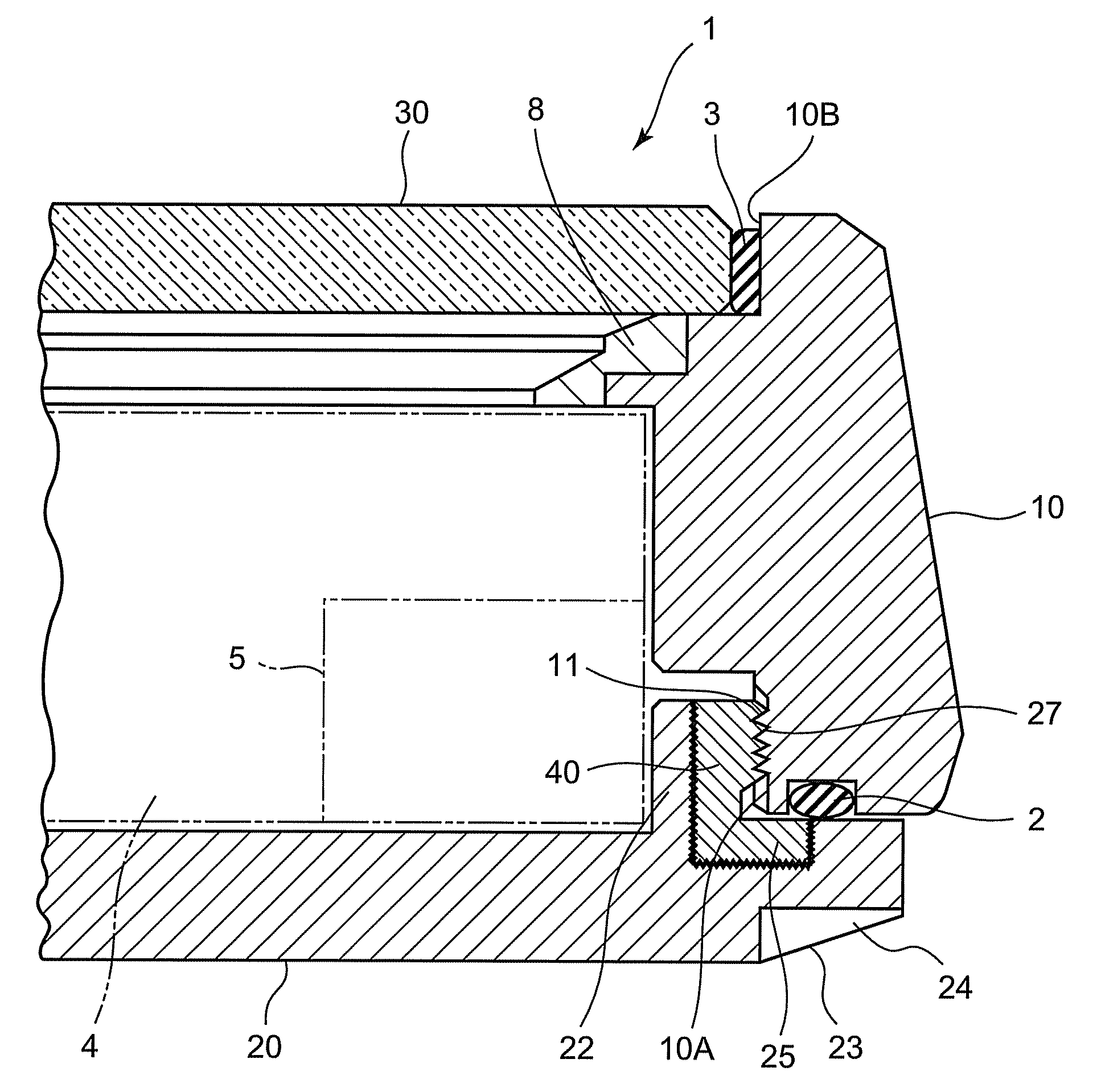
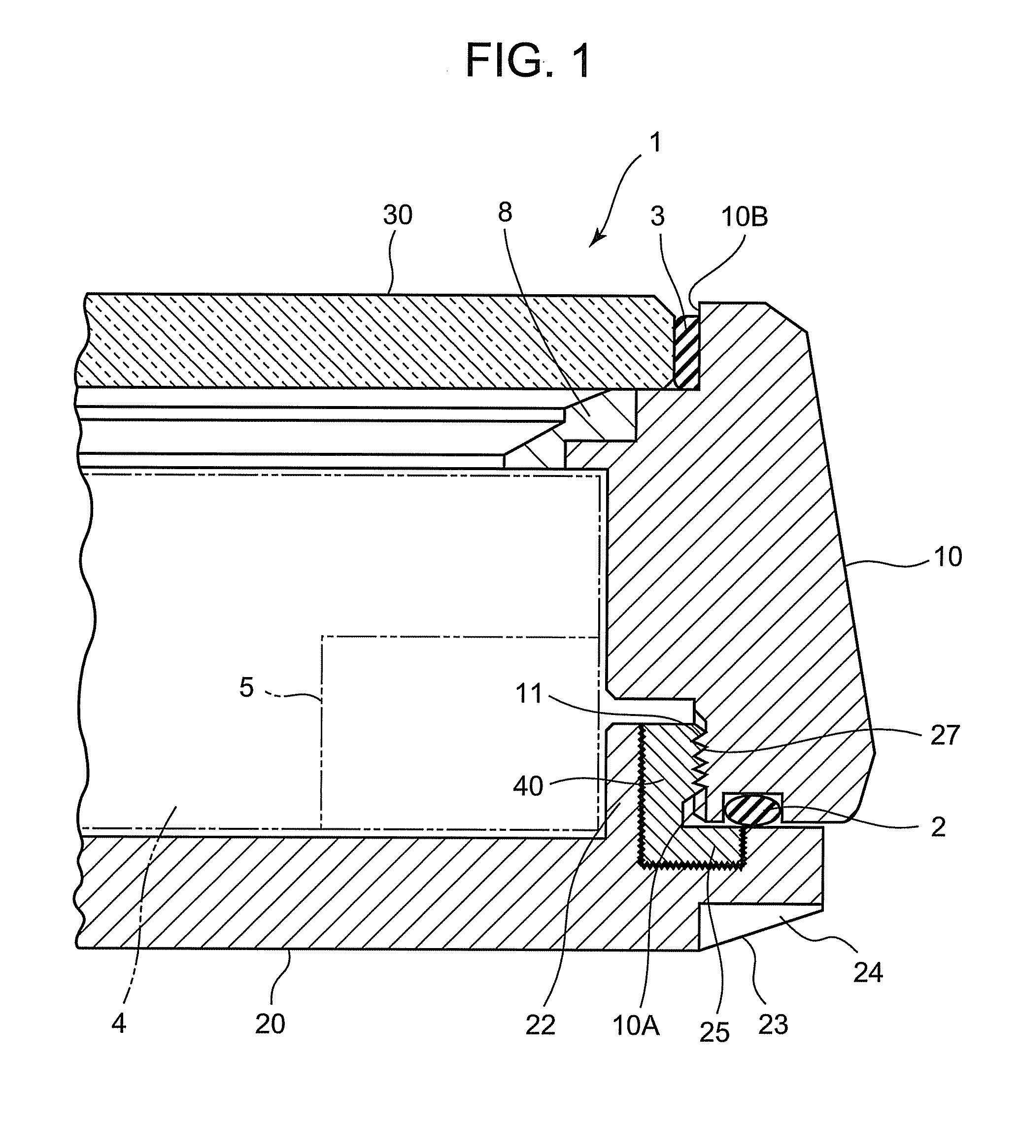
[0031]FIG. 1 is a sectional view illustrating a part of a radio-controlled timepiece according to the first embodiment of the present invention, and FIG. 2 is an enlarged sectional view illustrating main parts of a case body and a rear case of the radio-controlled timepiece.

[0032]A radio-controlled timepiece 1 according to the first embodiment includes a case body 10 which is a cylindrical device body, a rear case 20 as a first closing member, and a timepiece glass 30 as a second closing member 30. An opening 10A at one end (first end) of the case body 10 is closed by the rear case 20, while an opening 10B at the other end (second end) of the case body 10 is closed by the timepiece glass 30 having radio wave permeability. A seal member 2 is interposed between the case body 10 and the rear case 20, while a seal member 3 is interposed between the case body 10 and the timepiece glass 30. With this structure, water-proof property in the case body 10 is secured.

[0033]Inside the case body...

second embodiment

[0059]FIG. 5 is a sectional view illustrating main parts of the case body 10 and the rear case 20 of the radio-controlled timepiece 1 according to the second embodiment.

[0060]The radio-controlled time piece 1 in the second embodiment is different from the radio-controlled timepiece 1 in the first embodiment in that the coupling resin member 40 is coupled to the case body 10, not to the rear case 20.

[0061]Specifically, in the radio-controlled timepiece 1 according to the second embodiment, a metallic annular protruding portion 22A formed with the screw portion 27 is provided to the rear case 20. On the other hand, a great number of irregularities 26 of a nanometer size are formed on the wall surface 10D-1 of the case body 10 facing a top wall surface of the annular protruding portion 22A and on the wall surface 10D-2 of the case body 10 facing an outer peripheral wall surface of the annular protruding portion 22A. The coupling resin member 40 is coupled to the case body 10 through th...

third embodiment

[0068]FIG. 6 is a sectional view illustrating main parts of the case body 10 and the rear case 20 in the radio-controlled timepiece 1 according to the third embodiment.

[0069]The radio-controlled time piece 1 in the third embodiment is different from the radio-controlled timepiece 1 in the first embodiment in that the rear case 20 does not have the metallic annular protruding portion 22.

[0070]Specifically, in the radio-controlled timepiece 1 according to the third embodiment, an annular recessed portion 25A is formed in the rear case 20, and a great number of irregularities 26 of nanometer size are formed on the wall surface of the annular recessed portion 25A. The coupling resin member 40 is coupled to the rear case 20 through the great number of irregularities 26. The coupling resin member 40 includes a filling portion 40A which is coupled to the wall surface of the annular recessed portion 25A through the great number of irregularities 26 and fills the annular recessed portion 25A...


PUM


Abstract

The radio wave receiver includes the metallic case body, the metallic rear case, and the antenna inside the case body. The screw portion is formed in the metal wall of the case body. The coupling resin member having an electrical insulating property is coupled to the rear case through a great number of fine irregularities formed in the metal wall thereof. The screw portion which engages with the screw portion is formed on the coupling resin member. The case body and the rear case are coupled to each other with the screw portions. The case body and the rear case are electrically insulated from each other by the electrical insulating function of the coupling resin member so as to improve receiving sensitivity of the antenna.

Description

CROSS-REFERENCE TO RELATED APPLICATIONS[0001]This application is based upon and claims the benefit of priority from the prior Japanese Patent Application No. 2010-292155 filed on Dec. 28, 2010, and the prior Japanese Patent Application No. 2011-273271 filed on Dec. 14, 2011, the entire contents of which are incorporated herein by reference.BACKGROUND OF THE INVENTION[0002]1. Field of the Invention[0003]The present invention relates to a radio wave receiver.[0004]2. Description of the Related Art[0005]As one of radio wave receivers, there has conventionally been known a radio-controlled timepiece which includes a case body (device body) and an antenna to receive a standard radio wave (standard time and frequency signal) containing time data inside the case body, wherein the time is corrected based upon the standard radio wave received by the antenna.[0006]The radio-controlled timepiece described above includes the one described below. Specifically, in order to achieve a high-quality ...

Claims


Application Information

Patent Timeline
Patent Type & Authority Patents(United States)
IPC IPC(8): H01Q1/24G04B37/11G04C3/00G04G21/04G04R60/12
CPCG04R60/12
Inventor YOKOO, KAZUMASASATO, JUNICHI
Owner CASIO COMPUTER CO LTD
Features
  • R&D
  • Intellectual Property
  • Life Sciences
  • Materials
  • Tech Scout
  • Unparalleled Data Quality
  • Higher Quality Content
  • 60% Fewer Hallucinations
Learn More