Method of boosting a local dimming signal, boosting drive circuit for performing the method, and display apparatus having the boosting drive circuit

a local dimming signal and drive circuit technology, applied in the direction of electric variable regulation, process and machine control, instruments, etc., can solve the problems of reducing the contrast ratio of an image displayed on the lcd panel, and affecting the operation of the display apparatus. the effect of power consumption

Active Publication Date: 2015-05-26
SAMSUNG DISPLAY CO LTD
View PDF16 Cites 1 Cited by
  • Summary
  • Abstract
  • Description
  • Claims
  • Application Information

AI Technical Summary

Benefits of technology

[0012]Example embodiments of the present invention provide a local dimming signal boosting method capable of decreasing power consumption.
[0015]According to one aspect of the present invention, there is provided a method of boosting a local dimming signal. In the method, it is determined whether or not local dimming signals, which are applied for individually driving light source blocks per frame, satisfy boosting conditions. Then, a predetermined local dimming signal corresponding to at least one of the light source blocks is boosted to a reference luminance value when the local dimming signals continuously satisfy the boosting conditions, and the boosting luminance of the predetermined local dimming signal at the reference luminance value is gradually decreased after a light adaptation time of an observer's eye.
[0024]The boosting driving part may include a counting part and a boosting part. The counting part may count the number of frames (hereinafter, a boosting frame number) which the predetermined dimming signal is boosted from a first boosting frame to a current boosting frame. The boosting part may boost the predetermined local dimming signal to the reference luminance value when the boosting frame number is smaller than the number of threshold frames, and may decrease the boosting luminance of the predetermined local dimming signal when the boosting frame number is greater than or equal to the number of threshold frames.
[0031]The boosting the predetermining dimming signals from the primary luminance value to the reference luminance value may increase a luminance value which the primary luminance value to the reference luminance value before a light adaptation time of an observer's eye.
[0032]Moreover, the boosting the predetermining dimming signals from the primary luminance value to the reference luminance value may increase a luminance value from the primary luminance value to the reference luminance value so as to substantially correspond with a distribution state according to a solid angle of a cone cell in an observer's eye. Here, the boosting the predetermining dimming signals from the primary luminance value to the reference luminance value may increase a luminance value in an exponential function form from the primary luminance value to the reference luminance value.
[0033]According to some example embodiments of the present invention, when the luminance of light source blocks that are boosted is gradually decreased before the light adaptation time or the luminance of light source blocks that will be boosted is gradually increased to the light adaptation time, power consumption required to boost the light source blocks may be decreased.

Problems solved by technology

However, it is difficult for the liquid crystal layer to be arranged in a uniform direction, so that light leakage may be generated when the LCD panel displays an image corresponding to a low gray level.
That is, it is difficult for the LCD panel to display a fully black image at a low gray level, so that the contrast ratio of an image displayed on the LCD panel may be decreased.
However, since the local boosting method is a technology which enhances the luminance of the predetermined light source blocks relative to the peripheral light source blocks, power consumption may be increased when the local boosting method is used.

Method used


Image

  • Method of boosting a local dimming signal, boosting drive circuit for performing the method, and display apparatus having the boosting drive circuit
  • Method of boosting a local dimming signal, boosting drive circuit for performing the method, and display apparatus having the boosting drive circuit
  • Method of boosting a local dimming signal, boosting drive circuit for performing the method, and display apparatus having the boosting drive circuit

Examples


example embodiment 1

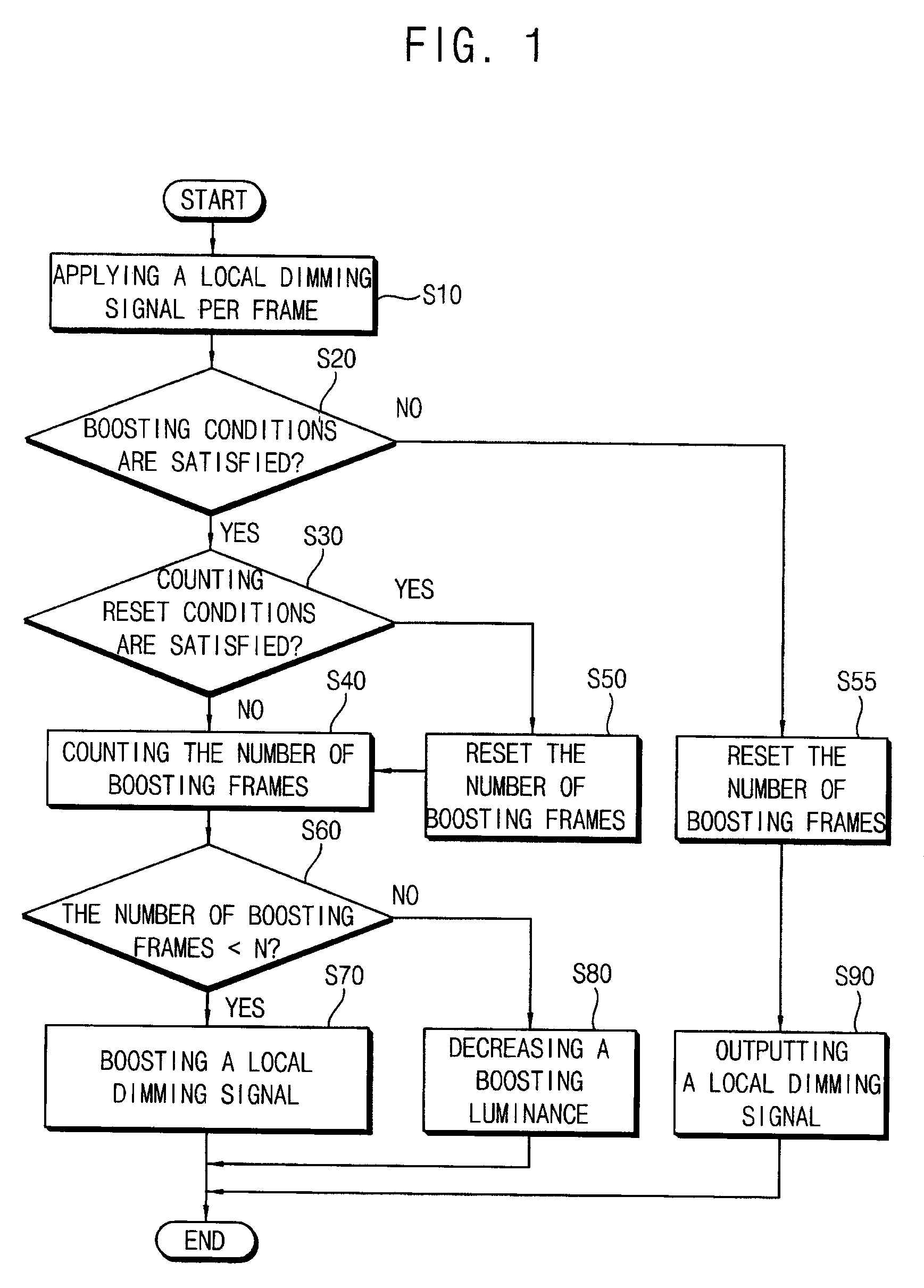
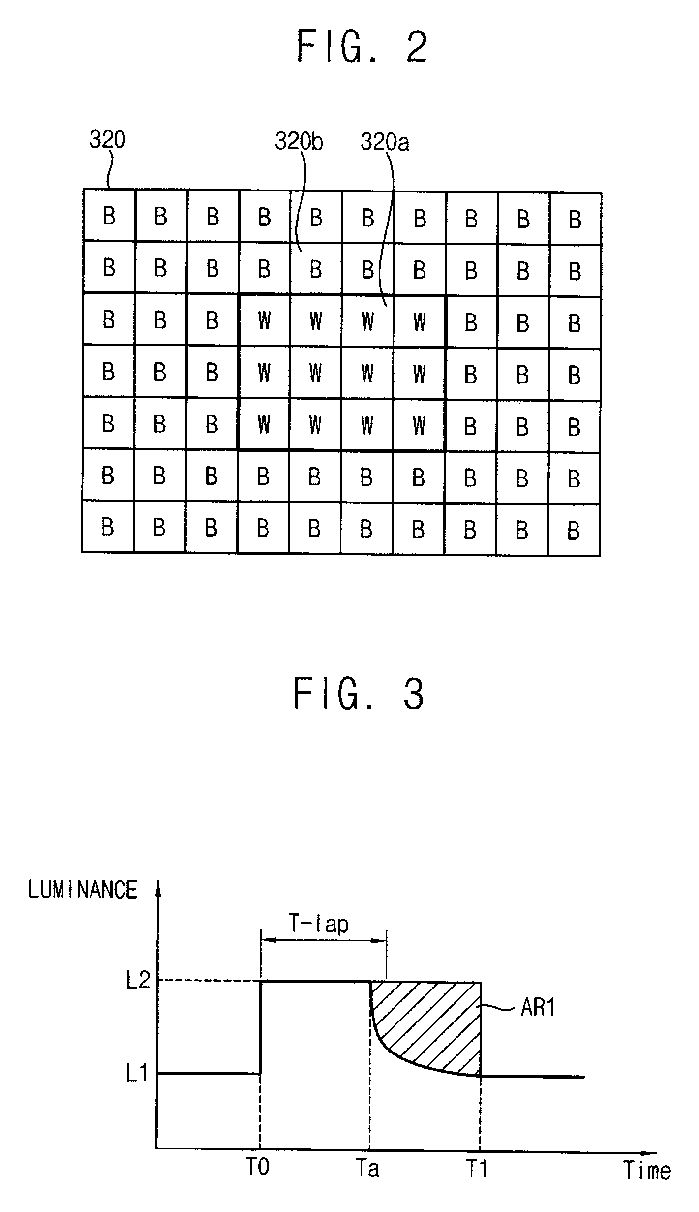
[0055]FIG. 1 is a flowchart diagram illustrating a method of boosting a local dimming signal according to Embodiment 1 of the present invention. FIG. 2 is a plan view illustrating a boosting condition of FIG. 1.

[0056]Referring to FIGS. 1 and 2, in a local dimming signal boosting method in accordance with the present embodiment, a local dimming signal for individually driving light source blocks 320 which generate light is received per frame (step S10).

[0057]In the present embodiment, the light source blocks 320 may be classified into at least one of a predetermined light source block 320a and remaining light blocks 320b except for the predetermined light source block 320a. For example, when the light source blocks 320 are arranged in seven rows and ten columns, the predetermined light source blocks 320a may be arranged in the center of the light source blocks 320 in three rows and four columns and the remaining light source blocks 320b may be arranged in a peripheral of the predeter...

example embodiment 2

[0122]FIG. 9 is a flowchart illustrating a method of boosting a local dimming signal according to Embodiment 2 of the present invention. FIG. 10 is a plan view illustrating a state in which the size of a white image is decreased in FIG. 9. FIG. 1 is a graph repeatedly illustrating a variation of the luminance of dimming signals that are boosted in local dimming signals. FIG. 12 is a waveform diagram illustrating a duty variation of dimming signals that are boosted in local dimming signals.

[0123]The display device used for the local dimming signal boosting method according to the present embodiment is substantially the same as the display device of FIGS. 1 to 8 except for at least a boosting method. Thus, the same reference numbers will be used to refer to the same or like parts as those described in Embodiment 1 and any further explanation concerning the above elements will be omitted.

[0124]Referring to FIGS. 9 to 12, in order to boost a local dimming signal in accordance with the p...


PUM


Abstract

There is provided a method of boosting a local dimming signal. In the method, it is determined whether or not local dimming signals, which are applied for individually driving light source blocks per frame, satisfy boosting conditions. Then, a predetermined local dimming signal corresponding to at least one of the light source blocks is boosted to a reference luminance value when the local dimming signals continuously satisfy the boosting conditions, and the boosting luminance of the predetermined local dimming signal at the reference luminance value is gradually decreased after a light adaptation time of an observer's eye. When the luminance of light source blocks that are boosted is gradually decreased before the light adaptation time or luminance of light source blocks that will be boosted is gradually increased to the light adaptation time, power consumption required to boost the light source blocks may be decreased.

Description

PRIORITY STATEMENT[0001]This application claims priority under 35 U.S.C. §119 to Korean Patent Application No. 10-2008-0052216, filed on Jun. 3, 2008, and Korean Patent Application No. 10-2008-0097489, filed on Oct. 6, 2008 in the Korean Intellectual Property Office (KIPO), the contents of which are herein incorporated by reference in their entireties.BACKGROUND OF THE INVENTION[0002]1. Field of the Invention[0003]Example embodiments of the present invention relate to a method of boosting a local dimming signal, a boosting drive circuit for performing the method, and a display apparatus having the boosting drive circuit. More particularly, example embodiments of the present invention relate to a method of boosting a local dimming signal capable of individually driving light source unit blocks, a boosting drive circuit for performing the method, and a display apparatus having the boosting drive circuit.[0004]2. Description of the Related Art[0005]Generally, a liquid crystal display (...

Claims


Application Information

Patent Timeline
Patent Type & Authority Patents(United States)
IPC IPC(8): G09G5/10G09G3/34H05B41/392H05B44/00
CPCH05B33/0818G09G3/3426H05B33/086H05B41/3927G09G2320/0633G09G2320/064G09G2330/021G09G2360/16H05B45/20H05B45/38
Inventor PARK, SE-KIOH, JOON-HAKKIM, GI-CHERLPARK, GI-CHANGKIM, JOONG-HYUNYEO, DONG-MINKWON, NAM-OKKWON, YONG-HOON
Owner SAMSUNG DISPLAY CO LTD
Why Eureka
Try Eureka