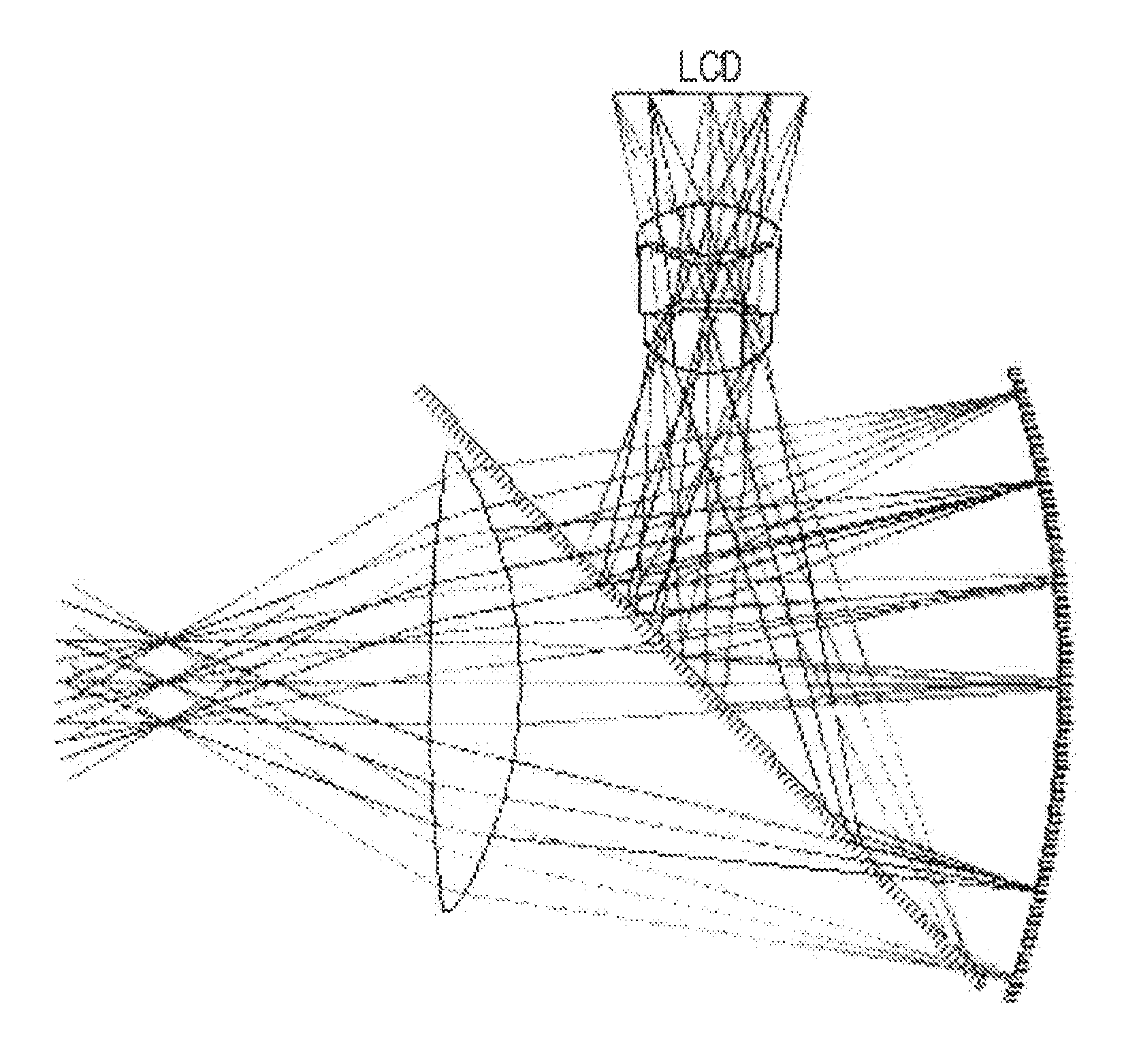
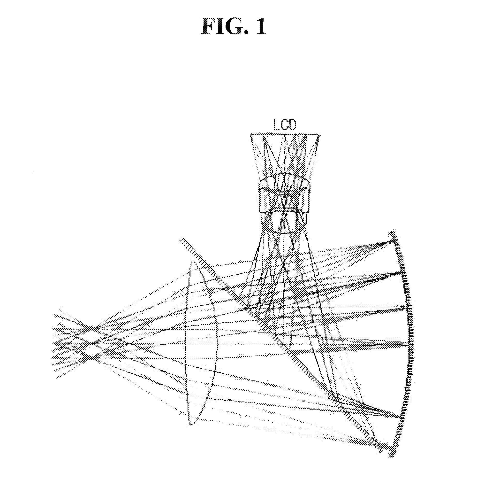
Optical system for head-mounted display
a technology of optical system and display, applied in the field of head-mounted displays, can solve the problems of increased resolution, reduced weight, and reduced resolution, and achieve the effects of improving resolution, large image, and improving angle of view
- Summary
- Abstract
- Description
- Claims
- Application Information
AI Technical Summary
Benefits of technology
Problems solved by technology
Method used
Image
Examples
first embodiment
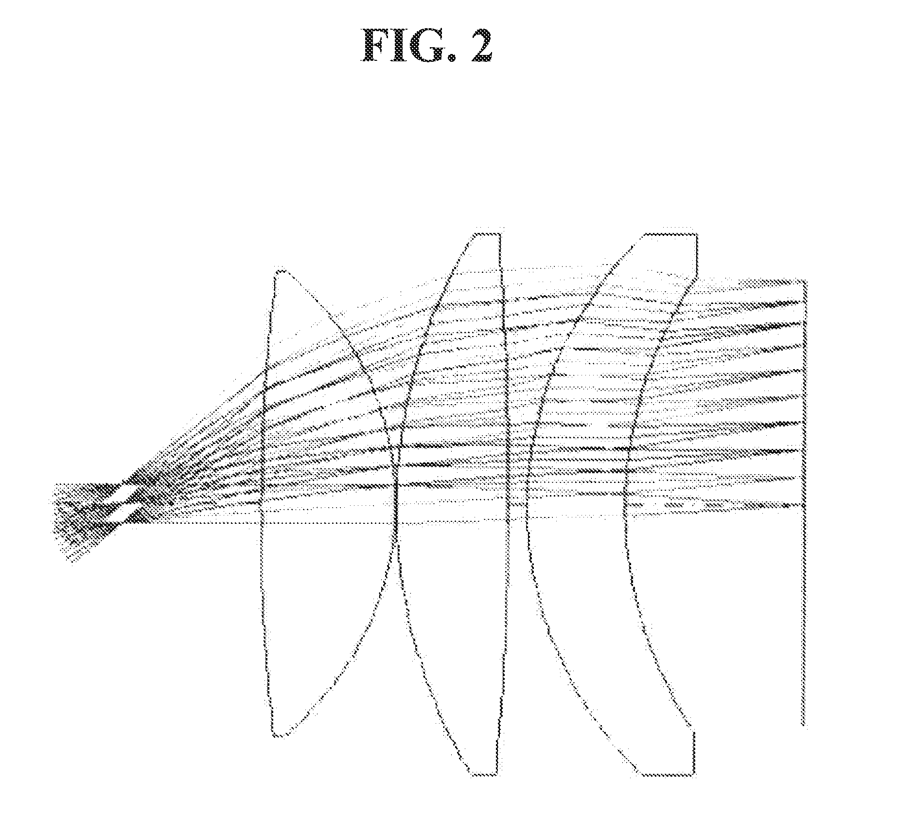
[0062]FIG. 3 shows an optical system for an HMD in accordance with a first embodiment of the present invention.
[0063]As shown, a first lens L1, a second lens L2, and a third lens L3 are arranged from the object along an optical axis in that order. Here, the object is a virtual object and refers to a distance which a user feels from an enlarged image when the user directly recognizes the enlarged image.
[0064]Numerical data of the lenses constituting the optical system according to the first embodiment of the present invention are shown in Table 1 below.
[0065]
TABLE 1Radius ofcurvatureThickness Refractive Abbe valuePlane No.(RDY)(THI)index (Nd)(Vd)OBJINFINITY2000STOINFINITY92−144.270483.51.63223.63−31.249962.392384414.2446831.63223.6516.048790.831839620.936864.2757771.53155.8721.7823625.000004IMGINFINITY0(OBJ: Object plane, STO: Stop, IMG: Image plane, and Infinity: Flat plane)
[0066]As shown in FIG. 3, the stop STO is disposed at the side of the object, and the first lens L1, the secon...
second embodiment
[0076]FIG. 4 shows an optical system for an HMD in accordance with a second embodiment of the present invention.
[0077]As shown, a first lens L1, a second lens L2, and a third lens L3 are sequentially arranged from the object along an optical axis. Here, the object is a virtual object and refers to a distance which a user feels from an enlarged image when the user directly recognizes the enlarged image.
[0078]Numerical data of the lenses constituting the optical system according to the second embodiment of the present invention are shown in Table 4 below.
[0079]
TABLE 4Radius ofcurvatureThicknessRefractiveAbbe valuePlane No.(RDY)(THI)index (Nd)(Vd)OBJINFINITY2000STOINFINITY9.5107542183.590936.4325651.53155.83−12.023830.3429.187662.1066851.63223.6516.654322.776617627.355562.5453631.49257.1719.1248420.279181IMGINFINITY0(OBJ: Object plane, STO: Stop, IMG: Image plane, and Infinity: Flat plane)
[0080]As shown in FIG. 4, the stop STO is disposed at the side of the object, and the first lens L...
third embodiment
[0088]FIG. 5 shows an optical system for an HMD in accordance with a third embodiment of the present invention.
[0089]As shown, a first lens L1, a second lens L2, and a third lens L3 are sequentially arranged from the object along an optical axis. Here, the object is a virtual object and refers to a distance which a user feels from an enlarged image when the user directly recognizes the enlarged image.
[0090]Numerical data of the lenses constituting the optical system according to the third embodiment of the present invention are shown in Table 7 below.
[0091]
TABLE 7Radius ofcurvatureThicknessRefractive Abbe valuePlane No.(RDY)(THI)index (Nd)(Vd)OBJINFINITY2000STOINFINITY9.510754234.411159.4523531.53155.83−64.071991.508083444.007022.61.63223.6531.296048.126665620.9096251.49257.1723.6392623.3129IMGINFINITY0(OBJ: Object plane, STO: Stop, IMG: Image plane, and Infinity: Flat plane)
[0092]As shown in FIG. 5, the stop STO is disposed at the side of the object, and the first lens L1, the seco...
PUM
 Abstract
Description
Claims
Application Information
 - R&D
- Intellectual Property
- Life Sciences
- Materials
- Tech Scout
- Unparalleled Data Quality
- Higher Quality Content
- 60% Fewer Hallucinations
Browse by: Latest US Patents, China's latest patents, Technical Efficacy Thesaurus, Application Domain, Technology Topic, Popular Technical Reports.
© 2025 PatSnap. All rights reserved.Legal|Privacy policy|Modern Slavery Act Transparency Statement|Sitemap|About US| Contact US: help@patsnap.com


