Stimulus artifact removal for neuronal recordings

a technology of neuronal recording and stimulus artifact, which is applied in the field of medical implants, can solve the problems of unintentional recording of stimulus waveform (also called stimulus artifact) from this mixture, unfavorable measurement accuracy, and inability to completely hold the invariance of a nap

Active Publication Date: 2015-06-02
MED EL ELEKTROMEDIZINISCHE GERAETE GMBH
View PDF8 Cites 50 Cited by
  • Summary
  • Abstract
  • Description
  • Claims
  • Application Information

AI Technical Summary

Problems solved by technology

The removal of the unintentional recorded stimulus waveform (also called the stimulus artifact) from this mixture has proven to be a difficult task.
But alternating stimulation creates an undesired increase in measurement time.
Moreover, the assumption of phase-invariance of an NAP does not hold completely.
As with alternating stimulation, the masker probe approach requires an undesirable increase in measurement time.
But the use of a triphasic pulse leads to an increased delay between the stimulus portion that triggers the NAPs and the beginning of the recording.
One disadvantage with that approach is that the artifact does not scale linearly with increasing amplitudes.

Method used


Image

  • Stimulus artifact removal for neuronal recordings
  • Stimulus artifact removal for neuronal recordings
  • Stimulus artifact removal for neuronal recordings

Examples


first embodiment

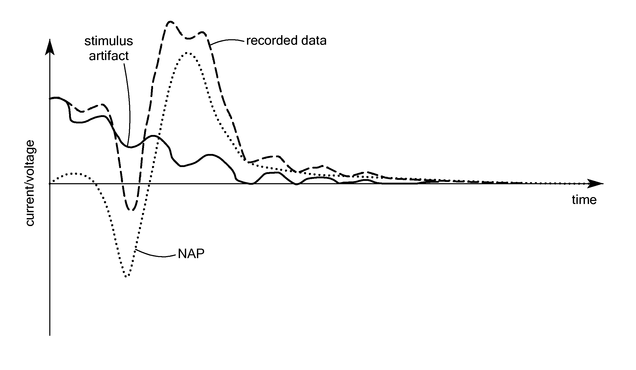
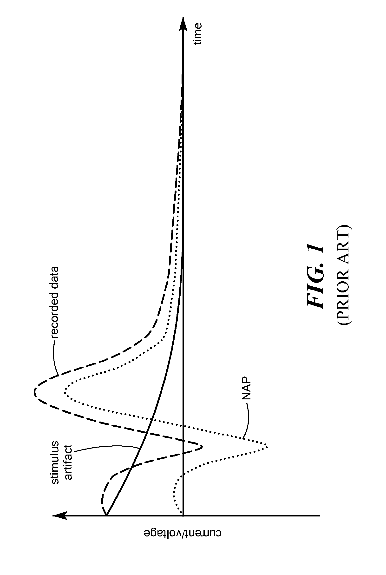
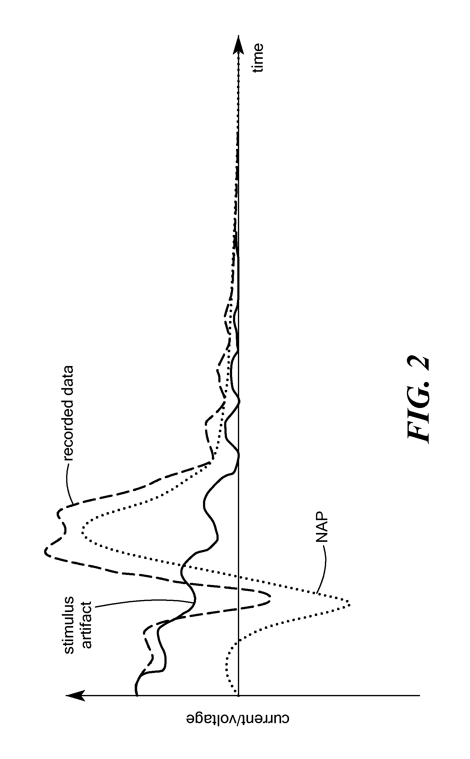
[0016]Initially, there are two situations where the derivation of a new stimulus artifact waveform can be performed. In a first embodiment, a general waveform is a priori derived using a database of existing NAP waveforms. For Source A (the stimulus artifact) a sampled waveform is defined as xA and for Source B (the NAP) another sampled waveform is defined as xB, which are vectors of length N where N is the number of measured samples. As the performance of the source separation algorithm directly correlates with the distance of xA and xB, an optimal new stimulus artifact waveform can be which maximizes this distance.

[0017]One simple way to measure such a distance would be a Euclidean metric, such that the new stimulus artifact waveform can be derived by maximizing a cost function:

[0018]C=sqrt⁢((xA⁡(1)+xB⁢⁢1⁡(1))2+(xA⁡(2)+xB⁢⁢1⁡(2))2+…+(xA⁡(N)+xB⁢⁢1⁡(N))2)+sqrt⁡((xA⁡(1)+xB⁢⁢2⁡(1))2+(xA⁡(2)+xB⁢⁢2⁡(2))2+⁢…+(xA⁢(N)+xB⁢⁢2⁡(N))2)+⁢…+sqrt(⁢(xA⁡(1)+xB⁢⁢M⁡(1))2+⁢(xA⁡(2)+xB⁢⁢M⁡(2))2+⁢…+⁢(xA⁡(...

second embodiment

[0019]In a second embodiment, a patient dependent waveform is derived dynamically. The stimulus artifact waveform is known, so the achieved separation performance for the actual measurement can be derived. The measurement starts with the a priori derived waveform as described above. Using standard optimization algorithms such as a gradient descent search, the stimulus artifact waveform can be changed to be optimized for the actual measured waveform signal so as to achieve an improved separation performance.

[0020]Note that additional post-processing of xA and xB such as by a principle component analysis-based dimension reduction can further improve the performance of the waveform derivation. Also a more specialized metric such as a weighted metric may also show further improvements.

[0021]The fast identification of the Source A in the recorded waveform signal mixture can be performed using, for example, a matched filter approach which results in a source separation system that can ope...


PUM


Abstract

A method is described for processing an electrical stimulation response measurement waveform signal measured in response to delivery of a selected electrical stimulation signal to neural tissue. The electrical stimulation response measurement waveform signal contains a stimulus artifact and one or more neuronal action potentials. The electrical stimulation signal is selected based on satisfying a cost function comparison between at least one stimulus artifact component and a plurality of known neuronal action potential waveforms. The electrical stimulation response waveform signal is then processed using a source separation algorithm to remove the stimulus artifact component.

Description

[0001]This application claims priority from U.S. Provisional Patent Application 61 / 097,611, filed Sep. 17, 2008, which is incorporated herein by reference.FIELD OF THE INVENTION[0002]The present invention relates to medical implants, and more specifically to diagnostic measurement in cochlear implant systems.BACKGROUND ART[0003]Recordings of neuronal action potentials (NAPs) evoked by close-by applied electrical stimulation provide a signal mixture containing two major components: (1) the desired NAPs, and (2) the applied electrical stimulus. The removal of the unintentional recorded stimulus waveform (also called the stimulus artifact) from this mixture has proven to be a difficult task.[0004]Various techniques have been used to eliminate or reduce the stimulus artifact from recordings of evoked compound action potentials (ECAP) in neuroprosthetic devices such as cochlear implants. In the alternating stimulation approach, two recordings are performed using anodic-cathodic and catho...

Claims


Application Information

Patent Timeline
Patent Type & Authority Patents(United States)
IPC IPC(8): A61N1/00A61B5/04A61N1/05G06K9/00G06K9/62
CPCA61B5/04001G06K9/00523G06K9/624A61N1/0541A61B5/4041A61B5/24A61N1/36038G06F2218/08G06F18/2134
Inventor STRAHL, STEFAN
Owner MED EL ELEKTROMEDIZINISCHE GERAETE GMBH
Why Eureka
Try Eureka