
Reactive power controller for controlling reactive power in a wind farm

a technology of reactive power and controller, which is applied in the direction of machine/engine, process and machine control, instruments, etc., can solve the problems of inefficient wind turbine operation, inability to control a large number of wind turbines with the same or nearly identical commands for compensating reactive power, and inefficient operation of wind turbines

Active Publication Date: 2015-06-02
GE INFRASTRUCTURE TECH INT LLC
View PDF57 Cites 29 Cited by
  • Summary
  • Abstract
  • Description
  • Claims
  • Application Information

AI Technical Summary

Benefits of technology

This solution enables efficient reactive power control, reducing stress on transformers and cabling, improving overall wind farm efficiency, and minimizing costs by allowing for precise management of reactive power across sub-grids.

Problems solved by technology

Each electrical and / or mechanical component may have independent or different operating limitations, such as current, voltage, power, and / or temperature limits, than other components.
Moreover, known wind turbines typically are designed and / or assembled with predefined rated power limits.
Such operation may result in inefficient wind turbine operation, and a power generation capability of the wind turbine may be underutilized.
As an adjustable power factor PF is desired, such as a power factor of one (PF=1), controlling a large number of wind turbines with the identical or nearly identical commands for compensating reactive power is not efficient.
Thus, long electrical connections between individual wind turbines and an electrical collector bar for collecting the energy provided by the individual wind turbines is an issue.

Method used


Image

  • Reactive power controller for controlling reactive power in a wind farm
  • Reactive power controller for controlling reactive power in a wind farm
  • Reactive power controller for controlling reactive power in a wind farm

Examples


Embodiment Construction

[0019]Reference will now be made in detail to the various embodiments, one or more examples of which are illustrated in each figure. Each example is provided by way of explanation and is not meant as a limitation. For example, features illustrated or described as part of one embodiment can be used on or in conjunction with other embodiments to yield yet further embodiments. It is intended that the present disclosure includes such modifications and variations.

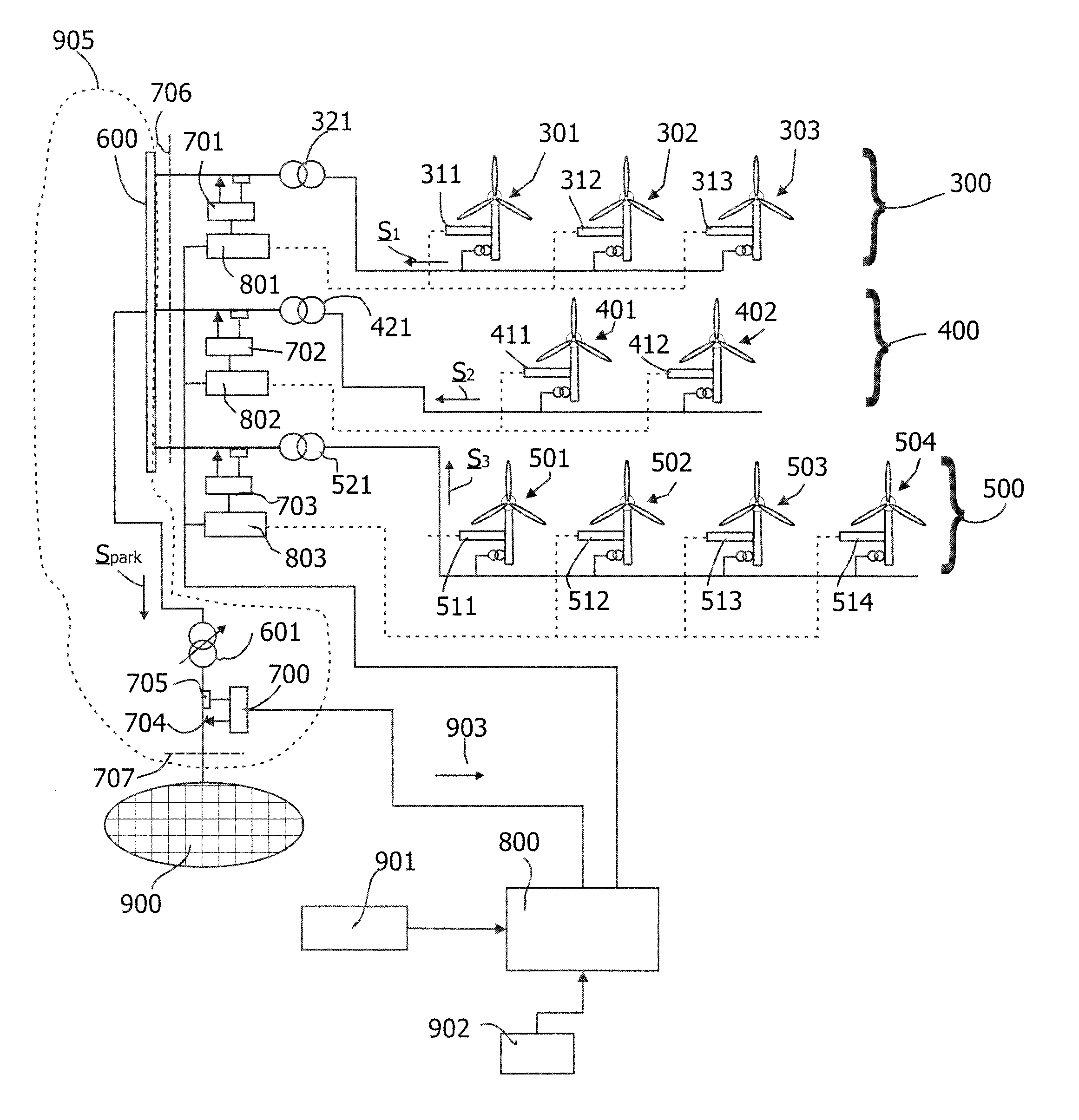
[0020]The embodiments described herein include a reactive power controller for a wind farm having a wind farm grid including at least two sub-grids electrically connected to each other. The reactive power controller includes a determination device such as a grid measurement device which is designed for measuring a reactive power component of electrical power generated by at least one wind turbine in the sub-grid. Furthermore, the reactive power controller includes a wind farm controller for controlling power generation at least ...


PUM


Abstract

A reactive power controller for controlling reactive power in a wind farm grid connected to a utility grid and including at least two sub-grids and a collector portion is provided. At least one wind turbine is connected to each sub-grid, wherein the at least two sub-grids are connected to the collector portion and wherein the collector portion establishes the connection to the utility grid. The reactive power controller includes a device for determining an actual reactive power value at the collector portion, and a wind farm controller operatively connected to the device for controlling at least one of said wind turbines on basis of the determined actual reactive power value such that a desired reactive power value is attained.

Description

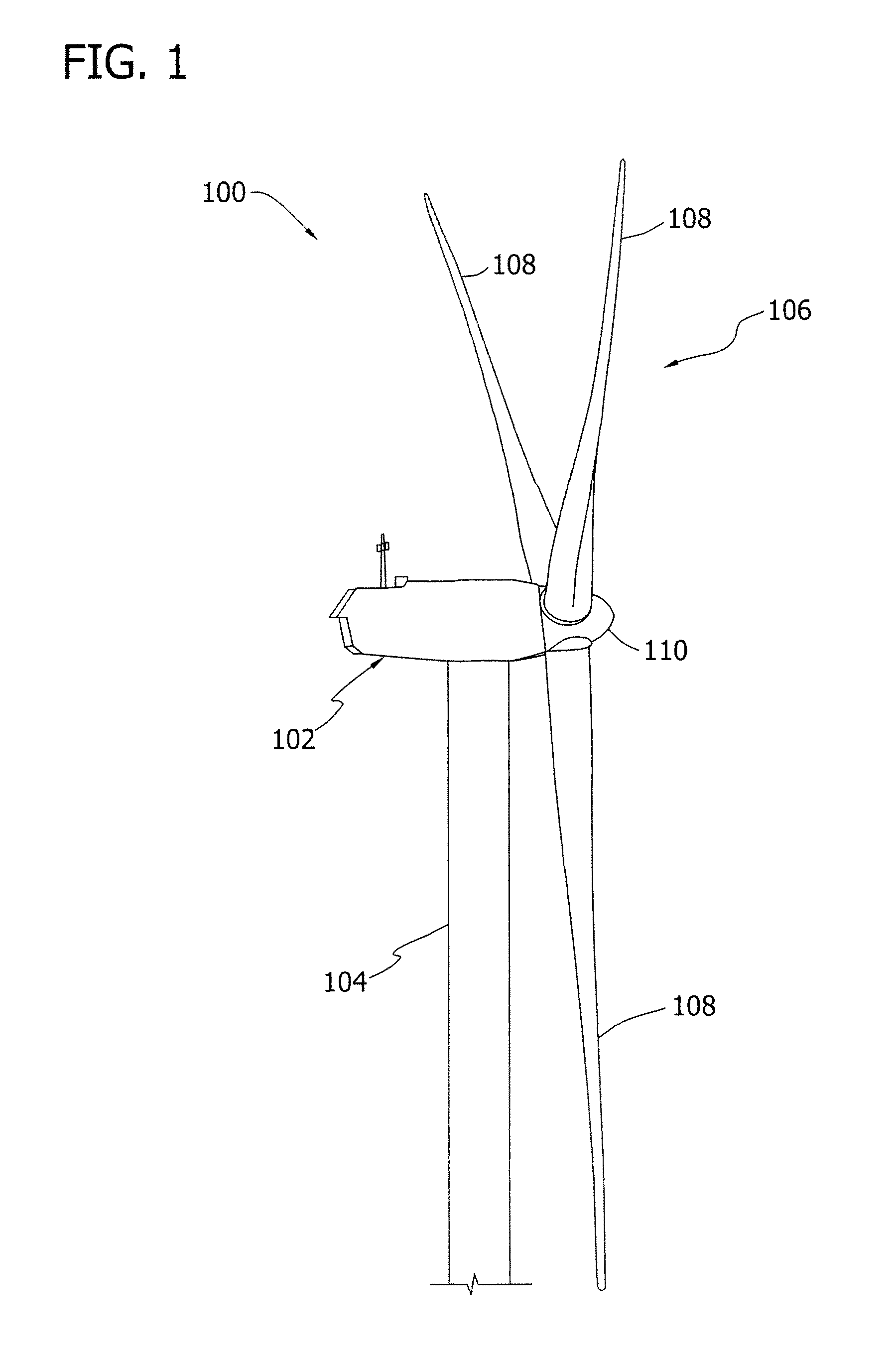
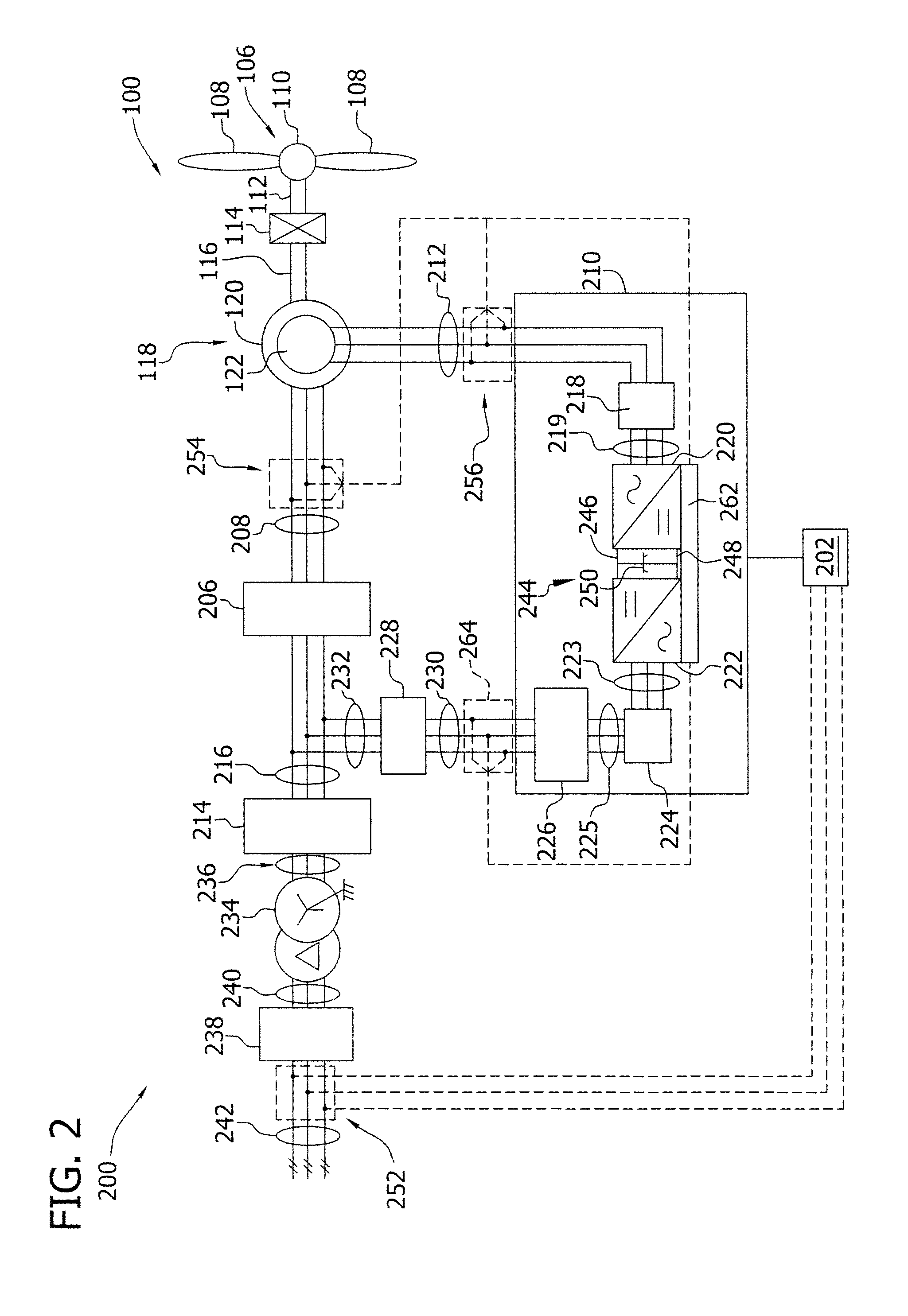
BACKGROUND OF THE INVENTION[0001]The subject matter described herein relates generally to systems for operating a plurality of wind turbines in a wind farm, and more particularly, to systems for controlling reactive power generated in the wind farm.[0002]Generally, a wind turbine includes a turbine that has a rotor that includes a rotatable hub assembly having multiple blades. The blades transform wind energy into a mechanical rotational torque that drives one or more generators via the rotor. The generators are sometimes, but not always, rotationally coupled to the rotor through a gearbox. The gearbox steps up the inherently low rotational speed of the rotor for the generator to efficiently convert the rotational mechanical energy to electrical energy, which is fed into a utility grid via at least one electrical connection. Gearless direct drive wind turbines also exist. The rotor, generator, gearbox and other components are typically mounted within a housing, or nacelle, that is p...

Claims


Application Information

Patent Timeline
Patent Type & Authority Patents(United States)
IPC IPC(8): G05D17/00F03D7/02F03D7/04F03D9/00H02J3/18H02J3/38H02J3/50
CPCF03D7/048F03D7/0284F03D9/003H02J3/18H02J3/386H02J3/50Y02E10/723Y02E10/763Y02E40/30F03D9/255F03D9/257H02J2300/28H02J3/381H02J3/46Y02E10/76Y02E10/72
Inventor KIRCHNER, ANDREASUBBEN, ENNOBRAAM, THOMAS
Owner GE INFRASTRUCTURE TECH INT LLC
Learn More