Fixing device and image forming apparatus capable of effectively suppressing thermal energy released externally from device due to thermal convection and hot air flow
a technology of thermal convection and hot air flow, which is applied in the direction of electrographic process apparatus, instruments, optics, etc., can solve the problems of heat escape from the inside of the fixing device, and achieve the effect of effectively suppressing thermal energy
- Summary
- Abstract
- Description
- Claims
- Application Information
AI Technical Summary
Benefits of technology
Problems solved by technology
Method used
Image

Examples
first embodiment
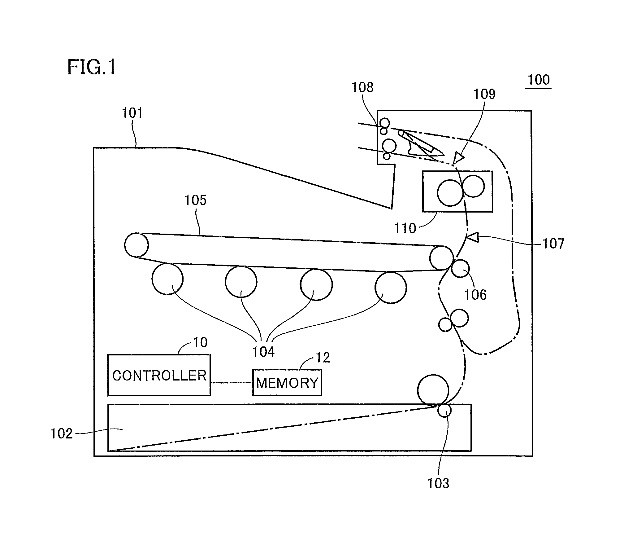
[0056]FIG. 1 is a view illustrating a structure of an image forming apparatus according to a first embodiment of the invention.
[0057]Referring to FIG. 1, an image forming apparatus 100 according to the first embodiment of the invention has an outer cover 101 covering a whole body of the apparatus, and a recording paper subjected to printing inside the apparatus body is discharged from a discharge opening 108.
[0058]For example, the apparatus body in this embodiment is a color printer of a tandem type forming color images.
[0059]Specifically, the example includes, for image formation, four rotating photoreceptors 104, an intermediate transfer belt 105 that successively layers toner images formed successively in respective transfer positions on photoreceptors 104 and transfers them, and a transfer roller 106 arranged in a transfer position that is set around a transportation plane of intermediate transfer belt 105. A sheet feed roller 103 transports the recording papers stored in a shee...
second embodiment
[0111]The first embodiment has been described in connection with the configuration that increases the heat retaining effect in fixing device 110 and thereby further reduces the warm-up time.
[0112]A second embodiment of the invention will be described in connection with a configuration that keeps good image quality.
[0113]FIG. 9 is a cross section of a fixing device 110P according to the second embodiment of the invention.
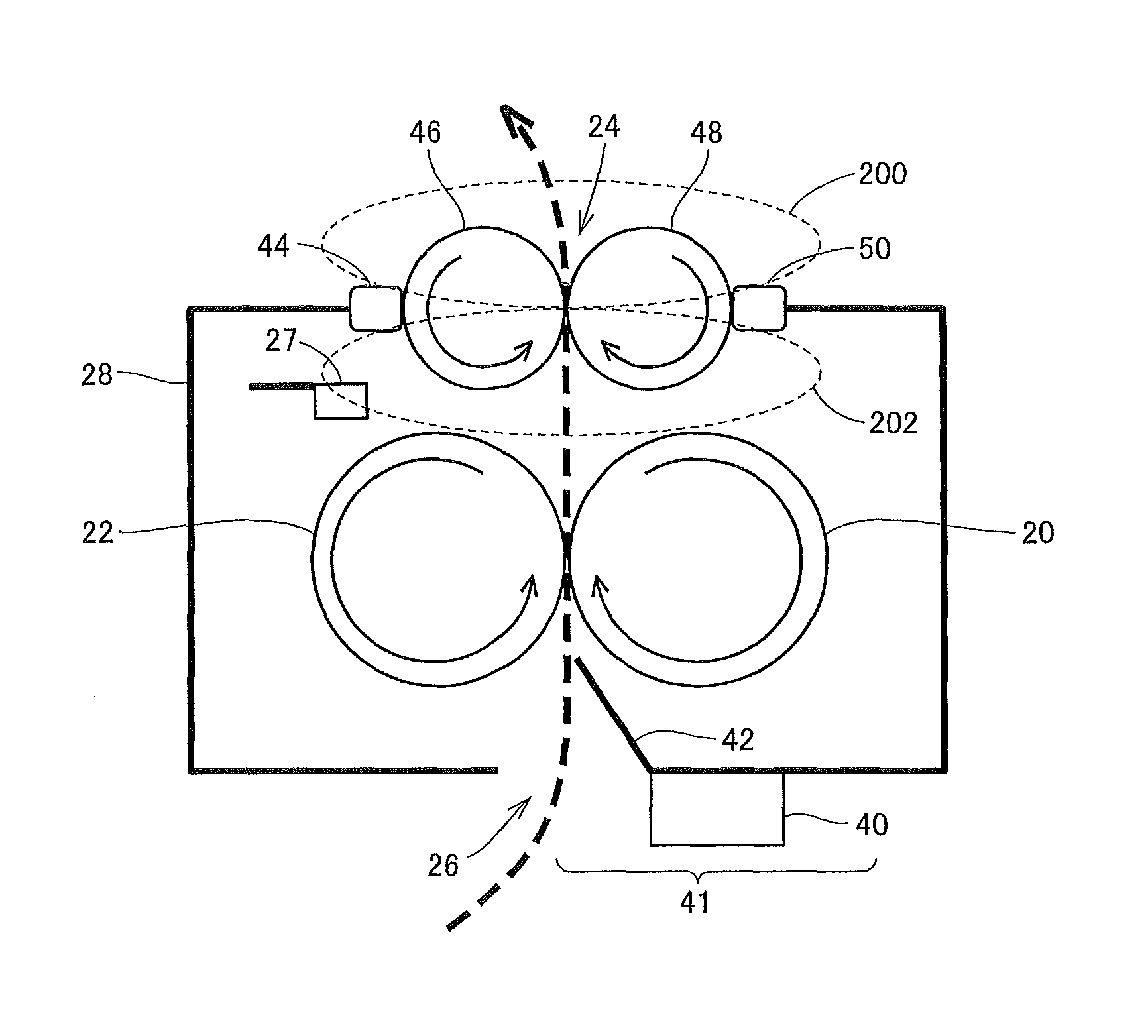
[0114]Referring to FIG. 9, fixing device 110P according to the second embodiment of the invention differs from fixing device 110 in that it includes temperature sensing unit 27 of a non-contact type for sensing an internal temperature of fixing device 110P. Other structures are substantially the same, and therefore description thereof is not repeated. Although not shown, temperature sensing unit for sensing the temperature of heating roller 22 is employed. The on / off of the halogen lamp is controlled based on a result of the temperature sensing by the temperature sen...
third embodiment
[0200]The second embodiment has been described in connection with the configuration uniformizing the surface temperatures by rotating heat-insulating rotation rollers 46 and 48 for suppressing the temperature difference that may occur between regions 200 and 202 of heat-insulating rotation rollers 46 and 48 during the warm-up, standby and the like.
[0201]However, when the surface temperature of heat-insulating rotation rollers 46 and 48 is low because only a short time elapsed since the start of printing, the quantity of heat applied to the recording paper is different from the quantity of heat that is applied to the recording paper when the surface temperature of heat-insulating rotation rollers 46 and 48 is high because the printing continued for a long time. In this case, variations occur in quantity of melted toner, and the gloss of the image changes.
[0202]A third embodiment will be described in connection with the configuration that performs control to prevent supplying of an ex...
PUM
 Abstract
Description
Claims
Application Information
 - R&D
- Intellectual Property
- Life Sciences
- Materials
- Tech Scout
- Unparalleled Data Quality
- Higher Quality Content
- 60% Fewer Hallucinations
Browse by: Latest US Patents, China's latest patents, Technical Efficacy Thesaurus, Application Domain, Technology Topic, Popular Technical Reports.
© 2025 PatSnap. All rights reserved.Legal|Privacy policy|Modern Slavery Act Transparency Statement|Sitemap|About US| Contact US: help@patsnap.com