Vehicle diagnostic method, and external diagnostic device

a diagnostic method and vehicle technology, applied in the direction of vehicle registration/indication, vehicle structure/machine measurement, registering/indicating working, etc., can solve the problems of operator difficulty in diagnosing the health state of the vehicle with accuracy, operator inability to recognize the possibility of deterioration in parts, etc., to avoid wrong operations, avoid the effect of waiting tim

Active Publication Date: 2015-06-02
HONDA MOTOR CO LTD
View PDF11 Cites 2 Cited by
  • Summary
  • Abstract
  • Description
  • Claims
  • Application Information

AI Technical Summary

Benefits of technology

[0007]The present invention has been made in view of the above problems. It is an object of the present invention to provide a vehicle diagnostic method and an external diagnostic apparatus which are capable of diagnosing the health state of a vehicle highly accurately.
[0009]According to the present invention, since the measurement (health state measurement) of the health state measuring step using the detected sensor values is inhibited until the vehicle has been warmed up, the health state of the vehicle can be measured accurately.
[0010]While the health state of the vehicle is inhibited from being measured, the varying states of the detected sensor values for judging a condition for inhibiting the measurement of the health state are displayed. Therefore, the user can confirm the reason why the measurement of the health state is inhibited, as the varying states in the detected sensor values, and can visually confirm the changing situation and how it changes until the inhibition of the measurement of the health state is canceled. In addition, in a case where it is taking more time than usual until the inhibition of the measurement of the health state is canceled, the user can recognize which one of the detected sensor values does not satisfy a condition for canceling the inhibition of the measurement of the health state. Therefore, the user is enabled to know that some trouble has been occurring in relation to the detected sensor value that does not satisfy the condition for canceling the inhibition of the measurement of the health state.
[0011]According to the present invention, furthermore, it is judged whether the detected sensor values are within the normal ranges or not only if the vehicle is idling. It is thus possible to measure the health state under a condition where the engine is operating stably, and hence the health state can be measured highly accurately.
[0013]Therefore, the varying states of the detected sensor values (the engine rotational speed, etc.) are displayed together with the first start button that is displayed as inactive until the displayed first start button goes from inactive to active. Consequently, information about whether the health state is inhibited from being measured or not is given to the user in a plain fashion. In addition, since the user is enabled to know the progress status of warming-up of the vehicle based on the varying states of the detected sensor values (the engine rotational speed, etc.), the user can avoid wrong operations during the waiting time.
[0014]The detected sensor values may include a coolant water temperature of the engine in addition to the engine rotational speed, and the varying state display step may display, on the operating screen, the varying states of the engine rotational speed and the coolant water temperature as animation images. Thus, the user can easily confirm the varying states of the engine rotational speed and the coolant water temperature, and can effectively use the waiting time until the inhibition of the measurement of the health state is canceled.

Problems solved by technology

However, if a long waiting time is needed until a measurement starting condition is met, e.g., the vehicle has been warmed up, then the operator tends to fail to recognize that there is a possibility of occurrence of deterioration in parts related to, for example, the long waiting time until the measurement starting condition is met, the reason why the measurement starting condition cannot be met, and the measurement starting condition.
Consequently, it is likely for the operator to have difficulty in diagnosing the health state of the vehicle with accuracy.

Method used


Image

  • Vehicle diagnostic method, and external diagnostic device
  • Vehicle diagnostic method, and external diagnostic device
  • Vehicle diagnostic method, and external diagnostic device

Examples


Embodiment Construction

A. Embodiment:

[1. Configuration]

(1-1. Overall Configuration)

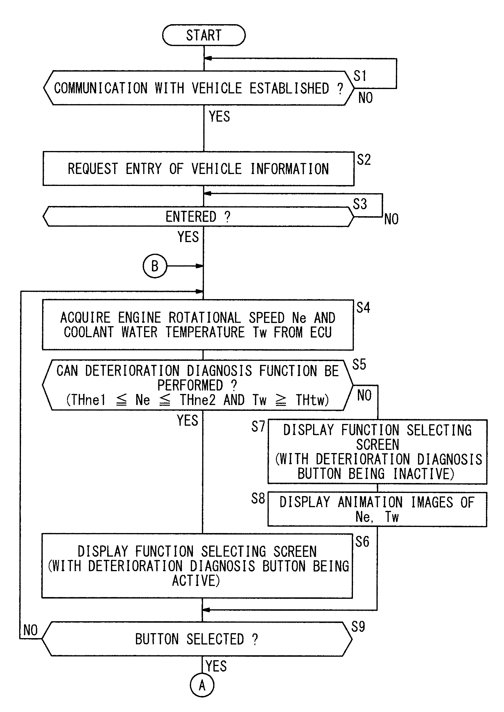
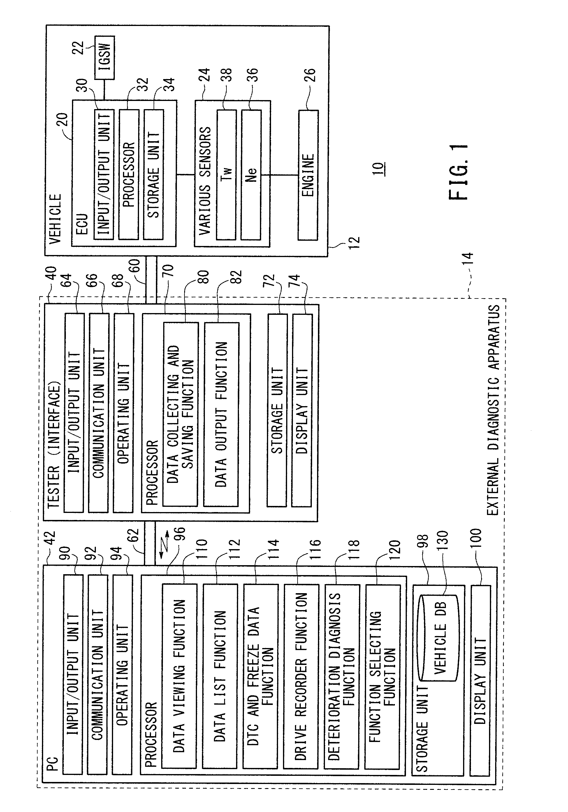
[0028]FIG. 1 shows in block form a general configuration of a fault diagnostic system 10 (hereinafter referred to as “system 10”) having an external diagnostic apparatus 14 (hereinafter referred to as “diagnostic apparatus 14”) according to an embodiment of the present invention. The system 10 includes a vehicle 12 (a motorcycle in the present embodiment) as a diagnostic target and the diagnostic apparatus 14 for making a fault diagnosis of the vehicle 12 from outside the vehicle 12.

(1-2. Vehicle 12)

[0029]The vehicle 12 has an electronic control unit 20 (hereinafter referred to as “ECU 20”), an ignition switch (hereinafter referred to as “IGSW 22”) for controlling on and off of the ECU 20, and various sensors 24. The ECU serves to control an engine 26, a transmission (not shown), a brake (not shown), etc. of the vehicle 12. As shown in FIG. 1, the ECU 20 has an input / output unit 30, a processor 32, and a storage unit 34.

[00...


PUM


Abstract

In a vehicle diagnostic method and an external diagnostic device, sensor detection values acquired by communicating with an ECU are measured to determine whether the values are in a normal range while a vehicle is idling. After an engine is started, an operation to measure soundness is prohibited at least until the sensor detection values including the engine rotational frequency reach a threshold value region indicating the completion of the warm-up operation. The fluctuation state of the sensor detection values is displayed on an operation screen until the sensor detection values reach the threshold value region.

Description

TECHNICAL FIELD[0001]The present invention relates to a vehicle diagnostic method and an external diagnostic apparatus (device) for making a diagnosis of the health state of a vehicle (deterioration diagnosis).BACKGROUND ART[0002]If a vehicle suffers a fault, the vehicle is taken to a repair shop of a dealer or the like. The operator (technician) who is responsible for repairing the vehicle connects an electronic control unit (hereinafter referred to as “ECU”) on the vehicle to an external diagnostic apparatus, reads fault data (fault code) from the ECU, analyzes a defective location or a fault source, and makes necessary repairs or an necessary adjustment.[0003]When vehicles are manufactured, they are checked at the final inspection stage of the production process to see if their sensors or ECUs are functioning properly or not. While vehicles to be diagnosed are conveyed one after another at the final inspection stage, each of the vehicles is controlled to operate (idle) stably and...

Claims


Application Information

Patent Timeline
Patent Type & Authority Patents(United States)
IPC IPC(8): G01M17/00G07C5/00G07C5/08
CPCG07C5/008G07C5/0808G07C2205/02
Inventor KAKINUMA, HIROYUKIITO, SAKAE
Owner HONDA MOTOR CO LTD
Why Eureka
Try Eureka