Membrane for a pressure dome

Active Publication Date: 2015-06-09
FRESENIUS MEDICAL CARE DEUTSCHLAND GMBH
View PDF14 Cites 5 Cited by
  • Summary
  • Abstract
  • Description
  • Claims
  • Application Information

AI Technical Summary

Benefits of technology

[0014]In particular, one task of the present invention is to provide a membrane for a pressure dome which is able to reduce to a minimum the possibility of air entering into the joint with the pressure sensor.
[0015]Anot

Problems solved by technology

These pressure domes, although widely used, are however not defect-free.
A first defect consists in the fact that air may infiltrate between the membrane and the sensor.
In such a case the sensor is no longer able to measure adequately the pressure of the chamber nor provide a reliable response with regard to variations thereof.
This problem is further exacerbated should the circuit have internally a negative pressure, i.e. a pressure lower than atmospheric pressure.
In such a case, which typically occurs upstream of the pumps located along the circuit, the membrane assumes a concave form, i.e. is “sucked” towards the inside of the pressure dome and worsen the precision of measurement.
Furthermore there exists the problem of ageing of the elastomer

Method used


Image

  • Membrane for a pressure dome
  • Membrane for a pressure dome
  • Membrane for a pressure dome

Examples


Embodiment Construction

[0026]Further scope of applicability of the present invention will become apparent from the detailed description given hereinafter. However, it should be understood that the detailed description and specific examples, while indicating preferred embodiments of the invention, are given by way of illustration only, since various changes and modifications within the spirit and scope of the invention will become apparent to those skilled in the art from this detailed description.

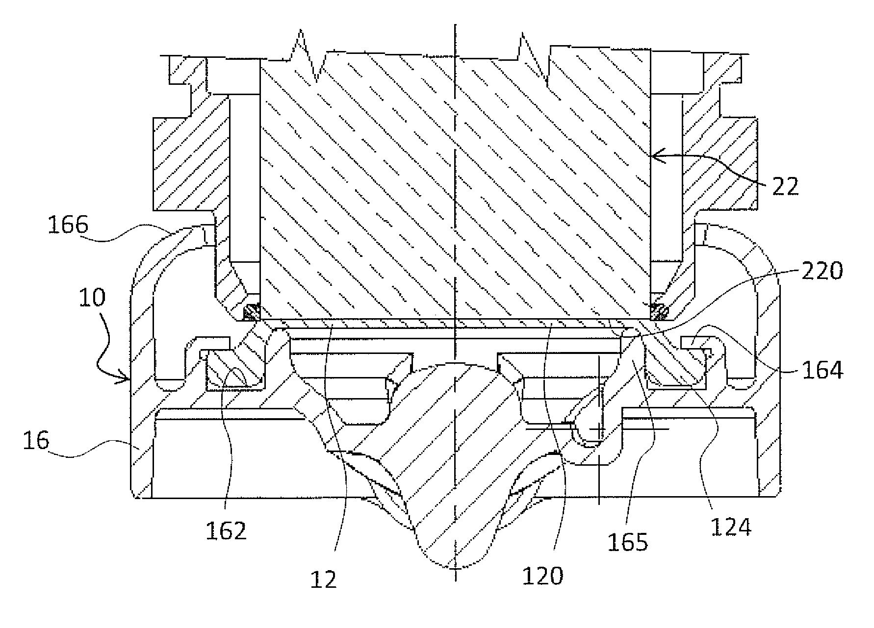
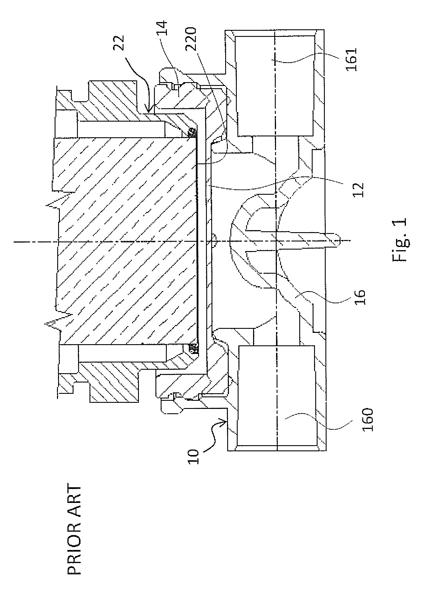
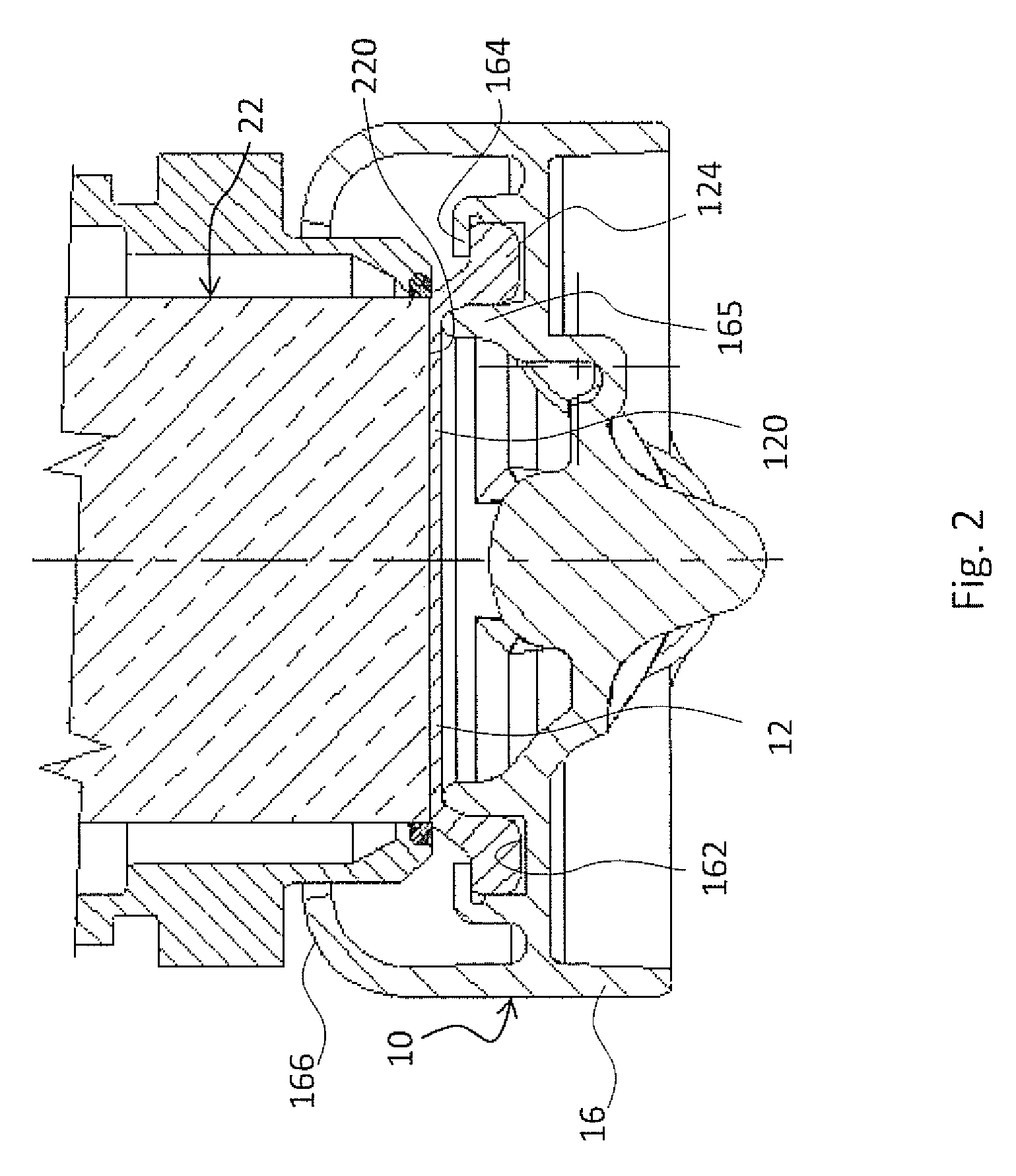
[0027]With reference to the accompanying figures, 10 denotes in its entirety a pressure dome comprising a membrane 12.

[0028]The membrane 12 according to the invention comprises:[0029]a resilient circular wall 120 suitable for closing one side of the pressure dome 10 so as to define a partition between the inside of the pressure dome and the outside;[0030]a circular rim 124 suitable for being joined to a main body 16 of the pressure dome 10;

whereby the resilient circular wall 120, when there is no difference betwe...


PUM


Abstract

A membrane for a pressure dome is configured to cooperate with a pressure sensor, and includes a resilient circular wall and a circular rim. The resilient circular wall is configured to close one side of the pressure dome so as to define a partition between the inside of the pressure dome and the outside. The circular rim is configured to be housed in a main body of the pressure dome. The membrane is configured such that the resilient circular wall, when there is no difference between the pressures acting respectively on the inner surface and on the outer surface, has an outwardly convex form.

Description

CROSS-REFERENCE TO RELATED APPLICATIONS[0001]This is a national stage of PCT / EP11 / 056321 filed Apr. 20, 2011 and published in English, which has a priority of Europe no. 10161554.0 filed Apr. 30, 2010, hereby incorporated by reference.BACKGROUND OF THE INVENTION[0002]1. Field of Invention[0003]The present invention relates to a chamber for measuring the pressure inside a pipe, in particular in an extra-corporeal circuit.[0004]2. Description of Prior Art[0005]During therapeutic treatment requiring extra-corporeal circulation, as for example in the case of hemodialysis, the pressure inside the circuit must be monitored. For this purpose, the machine used for the therapeutic treatment usually comprises suitably designed sensors. It is obviously necessary to prevent the fluids contained in the circuit from contaminating these sensors which are intended to be used repeatedly. On the other hand, the extra-corporeal circulation is performed in a disposable circuit.[0006]For this purpose it...

Claims


Application Information

Patent Timeline
IPC IPC(8): G01L7/08A61M1/36G01L19/14
CPCA61M1/3639G01L19/14A61M1/3641G01L7/08
Inventor FINI, MASSIMOREITER, REINHOLDDONARINI, LUCA
Owner FRESENIUS MEDICAL CARE DEUTSCHLAND GMBH
Why Eureka
Try Eureka