Image forming device, process cartridge engaged with the same and method for firmly positioning process cartridge in image forming device

a technology of image forming device and process cartridge, which is applied in the direction of optics, instruments, electrography/magnetography, etc., can solve the problems of large thrust force, affecting the positioning accuracy of the process cartridge in the image forming device, and high performance requirements of the spring, so as to reduce the vibration of the photosensitive drum during the image forming process, facilitate installation, and ensure the effect of positioning

Active Publication Date: 2015-06-09
ZHUHAI PANTUM ELECTRONICS
View PDF20 Cites 3 Cited by
  • Summary
  • Abstract
  • Description
  • Claims
  • Application Information

AI Technical Summary

Benefits of technology

[0006]The invention provides an image forming device, a process cartridge engaged with the same and a method for firmly positioning the process cartridge in the image forming device, to solve the technical problem that the image quality is affected by the low positioning accuracy of the process cartridge in the traditional image forming device.
[0020]By adoption of the technical proposal, as installation sections are arranged at the tail ends of guide rails and the installation sections and the guide rails approximately form barbs, lugs formed at both ends of a housing of the process cartridge are driven by a radial component of driving force of the image forming device to the process cartridge to always closely lean against the walls of the installation sections at the tail ends of the guide rails when the process cartridge is in the operating state in the image forming device. Therefore, not only the installation is convenient but also the positioning is reliable; the vibration of the photosensitive drum during the image forming is reduced; and the technical problem that the image quality is affected by the low positioning accuracy of the process cartridge in the traditional image forming device is solved.

Problems solved by technology

However, the position bears large thrust force; the performance requirement of the springs is relatively high; and the positioning accuracy of the process cartridge in the image forming device is affected.
Moreover, although the engagement mode of the traditional image forming device and process cartridge is simple, the process cartridge 10 can be driven to be disengaged from the installation position when the photosensitive drum driving gear 15 of the process cartridge 10 is under the action of the driving force of the main frame driving gear 5 of the image forming device, and consequently the image quality is poor.

Method used


Image

  • Image forming device, process cartridge engaged with the same and method for firmly positioning process cartridge in image forming device
  • Image forming device, process cartridge engaged with the same and method for firmly positioning process cartridge in image forming device
  • Image forming device, process cartridge engaged with the same and method for firmly positioning process cartridge in image forming device

Examples


Embodiment Construction

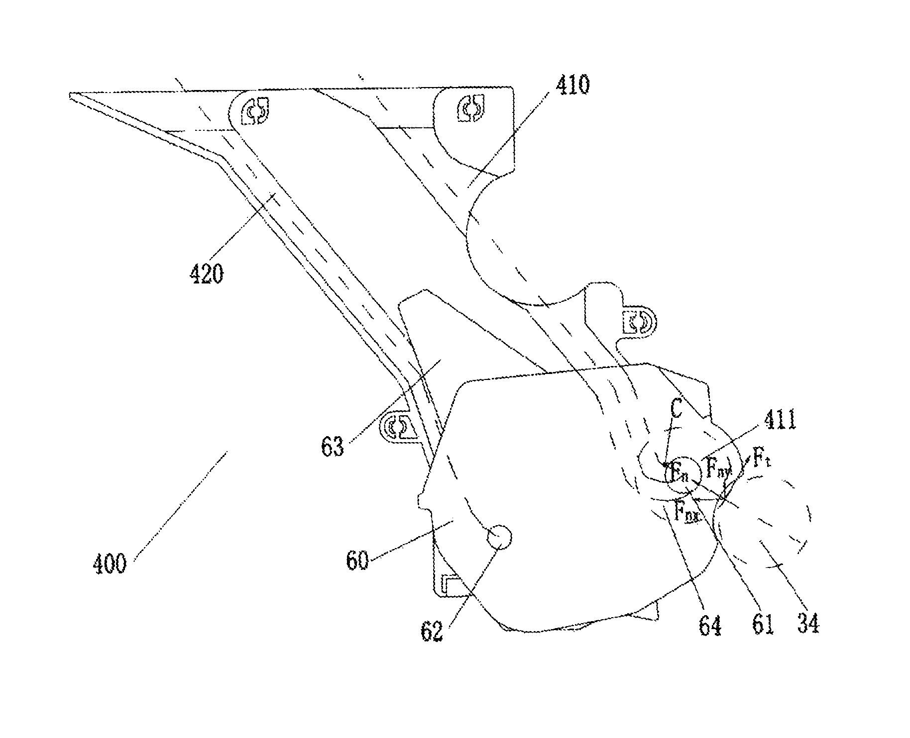
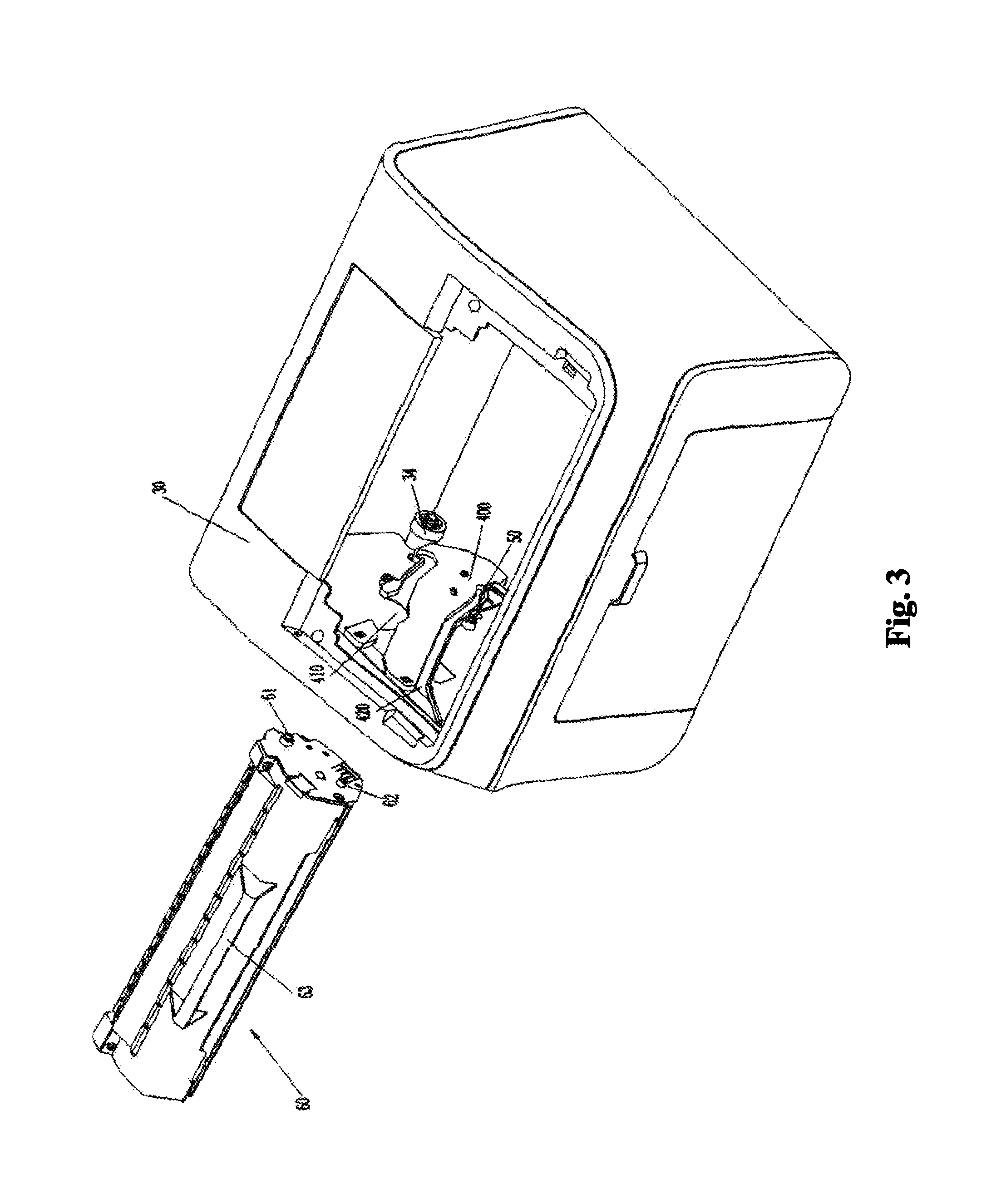
[0030]As illustrated in FIGS. 3 and 4, the image forming device comprises a main frame 30 and guide rails 400 which are arranged on the left and right sides of the inside of the main frame 30, wherein first guide rails 410 and second guide rails 420 are arranged on the guide rails 400; the guide rails approximately adopt top-down design; circular-arc installation sections 411 are arranged at the tail ends of the first guide rails 410; the installation sections 411 and the first guide rails 410 approximately form barbs; vertexes B of the installation sections 411 are higher than intersection points C of the installation sections 411 and the first guide rails 410, so the barbs are formed; and end points O of path centerlines AO of the installation sections 411 are higher than starting points A thereof.

[0031]Lower parts DB of the installation sections 411 are circular arcs of which the curvature is different from that of the guide rails. Due to the arrangement of the circular arcs, the...


PUM


Abstract

An image forming device, a process cartridge engageable with the same and a method for firmly positioning the process cartridge in the image forming device. The image forming device includes a main frame and a main frame driving gear, wherein a guide rail is respectively arranged on left and right sides of the inside of the main frame. An installation section is arranged at a tail end of each guide rail and the installation section and guide rail respectively define a reverse hook-shape. Lugs formed at both ends of a housing of the process cartridge are driven by a radial component of driving force of the image forming device to the process cartridge to closely bear against walls of installation sections at the tail ends of the guide rails when the process cartridge is in an operating state in the image forming device.

Description

[0001]This application is a national stage entry in the United States of PCT / CN11 / 77304 filed Jul. 19, 2011 and claims priority to Chinese application 201010234519.8 filed Jul. 22, 2010.FIELD OF THE INVENTION[0002]The invention relates to an image forming device, a process cartridge engaged with the same and a method for firmly positioning the process cartridge in the image forming device.BACKGROUND OF THE INVENTION[0003]The electrophotographic image forming device is a device for forming an image on a recording material by electrophotographic imaging processing, for example, an electrophotographic copier, an electrophotographic printer (a laser printer, an LED printer, etc.), a facsimile apparatus, a word processor and the like.[0004]FIG. 1 is a schematic diagram illustrating the engagement of the traditional process cartridge and image forming device. The traditional image forming device comprises a main frame 1 for the image forming device and a process cartridge 10 slideably cou...

Claims


Application Information

Patent Timeline
Patent Type & Authority Patents(United States)
IPC IPC(8): G03G21/18
CPCG03G21/1842G03G21/1853G03G21/1864G03G21/185
Inventor WU, LIANJUN
Owner ZHUHAI PANTUM ELECTRONICS
Why Eureka
Try Eureka