Dynamic stable endurance wireless charging system for unmanned aerial vehicle

A dynamic and stable wireless charging technology, applied in electric vehicle charging technology, charging stations, motor vehicles and other directions, can solve the problems of restricting the development of drones, insufficient battery power, limited battery life, etc., to achieve dynamic and stable battery life wireless charging, Improve overall efficiency and improve the effect of coupling coefficient

Inactive Publication Date: 2018-06-12
WUHAN UNIV
View PDF4 Cites 12 Cited by
  • Summary
  • Abstract
  • Description
  • Claims
  • Application Information

AI Technical Summary

Problems solved by technology

[0004] At present, drone technology is developing rapidly, but the problems of insufficient battery power and limited battery life have not been resolved, which limits the development of drone applications.

Method used


Image

  • Dynamic stable endurance wireless charging system for unmanned aerial vehicle
  • Dynamic stable endurance wireless charging system for unmanned aerial vehicle
  • Dynamic stable endurance wireless charging system for unmanned aerial vehicle

Examples


Embodiment Construction

[0018] Embodiments of the present invention will be described in detail below in conjunction with the accompanying drawings.

[0019] Examples of the described embodiments are shown in the drawings, wherein like or similar reference numerals designate like or similar elements or elements having the same or similar functions throughout. The embodiments described below by referring to the figures are exemplary only for explaining the present invention and should not be construed as limiting the present invention.

[0020] The following disclosure provides many different embodiments or examples for implementing different structures of the present invention. To simplify the disclosure of the present invention, components and arrangements of specific examples are described below. They are examples only and are not intended to limit the invention. Furthermore, the present invention may repeat reference numerals and / or letters in different instances. This repetition is for the pur...


PUM


Abstract

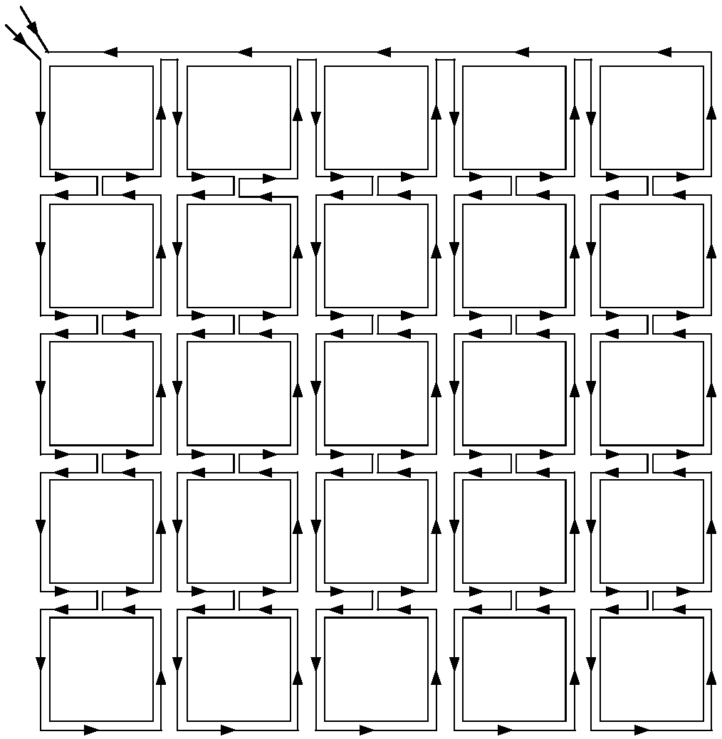
The invention relates to the technical field of magnetic coupling resonance type wireless power transfer, in particular to a dynamic stable endurance wireless charging system for an unmanned aerial vehicle. The system comprises the unmanned aerial vehicle, a charging platform, a power transmitting unit and a power receiving unit, the power transmitting unit is arranged in the charging platform, and the power receiving unit is arranged on the unmanned aerial vehicle; the power transmitting unit transmits energy to the power receiving unit. By means of the wireless charging system, the error-tolerant rate between a transmission coil and a receiving coil is increased; dynamic stable endurance wireless charging can be achieved; a matrix type transmission coil is adopted, the coupling coefficient between the transmission coil and the receiving coil is increased, and the overall efficiency of the system is improved; the receiving coil adopts a three-dimensional five-coil structure, and the intensity of a magnetic field parallel to the plane where the transmission coil and the receiving coil are located is fully utilized; therefore, waste of a transmission coil non-directional magnetic field is reduced, and by means of a positioning auxiliary cover installed above a charging area, the requirement of the positioning precision is lowered.

Description

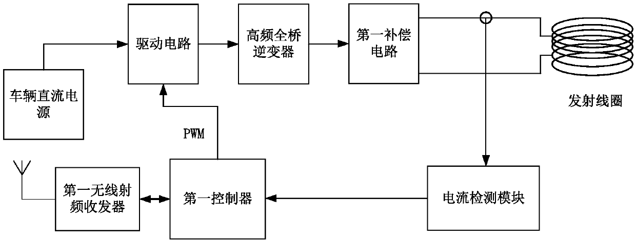
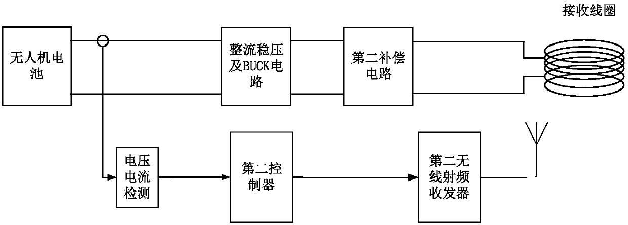
technical field [0001] The invention belongs to the technical field of magnetic coupling resonant wireless power transmission, and in particular relates to a wireless charging system for dynamic and stable battery life of unmanned aerial vehicles. Background technique [0002] According to different transmission mechanisms, wireless power transmission technology is mainly divided into four forms: electromagnetic radiation, electric field coupling, magnetic coupling resonance and ultrasonic coupling. The basic principle of magnetic coupling resonant wireless power transmission technology is: through the high-frequency inverter circuit, the direct current is converted into high-frequency alternating current, and the coils on both sides of the transmitting end and the receiving end undergo self-resonance under the cooperation of the compensation capacitor, so that the coil loop impedance value A minimum is reached, so that most of the energy oscillates back and forth between th...

Claims


Application Information

Patent Timeline
Patent Type & Authority Applications(China)
IPC IPC(8): H02J50/12H02J7/00B60L11/18
CPCB60L53/12B60L2200/10H02J7/025H02J50/12Y02T10/70Y02T10/7072Y02T90/14Y02T90/16
Inventor 王军华蔡昌松李国城张帆胡妹林林中正方支剑
Owner WUHAN UNIV
Why Eureka
Try Eureka