Method for setting the actuating force applied by a parking brake

a technology of parking brake and clamping force, which is applied in the direction of braking systems, instruments, analogue processes for specific applications, etc., can solve the problems of excessively low clamping force level to be set, reduced actuation of electric actuators, and insufficient reliability of hydraulic pressure information in the system. , to achieve the effect of sufficient degree of accuracy

Active Publication Date: 2015-06-16
ROBERT BOSCH GMBH
View PDF12 Cites 5 Cited by
  • Summary
  • Abstract
  • Description
  • Claims
  • Application Information

AI Technical Summary

Benefits of technology

[0005]An object of the present invention is to provide the clamping force of a parking brake having a mechanical brake device, including additional hydraulic support, with a sufficient degree of accuracy, by using simple means.
[0012]The actuator path is ascertained between two characteristic reference points. For example, it is advantageous to ascertain a free travel in the actuator actuating movement which the actuator completes between a first reference point and a force increase point, at which the force increase of the electromechanical clamping force begins. The first reference point coincides, for example, with the stopping point of the actuator in the retracted out-of-operation state. The force increase point may be relatively easily ascertained as the distinctive point in the curve of the motor state variables. In particular, the current curve of an electric brake motor corresponds to the force curve of the provided electromechanical clamping force, so that the force increase point may be inferred from the rise in the current curve, starting from a no-load current, during clamping or closing of the electromechanical brake device. The force increase point corresponds to the no-load point, since the electric actuator does not yet transmit any clamping force until this point is reached.

Problems solved by technology

This results in a correspondingly reduced actuation of the electric actuator of the electromechanical brake device and thus causes an excessively low clamping force level to be set.
If the comparison shows that the pressure reference path and the actuator path deviate significantly from each other, it must be assumed that the information about the hydraulic pressure in the system is not sufficiently trustworthy.
In the case of a measured pressure, in particular, an insufficient plausibility must be assumed if the pressure reference path deviates from the actuator path.
As described above, this admission pressure may result in a shifting during the course of the clamping force, with the result that the parking brake assumes a higher effective clamping force than is actually the case.

Method used


Image

  • Method for setting the actuating force applied by a parking brake
  • Method for setting the actuating force applied by a parking brake
  • Method for setting the actuating force applied by a parking brake

Examples


Embodiment Construction

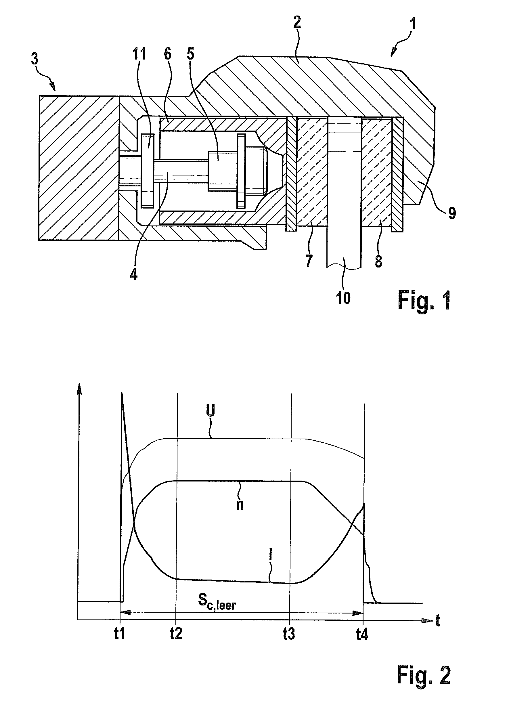
[0021]FIG. 1 shows an electromechanical parking brake 1 for holding a vehicle at a standstill. Parking brake 1 includes a brake caliper 2 having a clamp 9 which grips a brake disk 10. As the actuator, parking brake 1 has an electric motor as brake motor 3, which rotationally drives a spindle 4 on which a spindle component 5 is rotatably mounted. When spindle 4 rotates, spindle component 5 is axially adjusted. Spindle component 5 moves within a brake piston 6, which is the carrier of a brake pad 7 which is pressed against brake disk 10 by brake piston 6. Another brake pad 8, which is fixedly held in place on clamp 9, is located on the opposite side of brake disk 10.

[0022]During a rotational movement of spindle 4, spindle component 5 may move axially forward within brake piston 6 in the direction of brake disk 10 or, in a reversed rotational movement of spindle 4, it may move axially backward until it reaches a stop 11. To generate a clamping force, spindle component 5 strikes the inn...


PUM


Abstract

In a method for setting the clamping force applied by a parking brake, which is generated by an electromechanical brake device and additionally by a hydraulic brake device as needed, the hydraulic pressure is ascertained, and the pressure is assigned a pressure reference path which is compared with an actuator path.

Description

CROSS REFERENCE TO RELATED APPLICATIONS[0001]The present application is the national stage entry of International Patent Application No. PCT / EP2011 / 072223, filed on Dec. 8, 2011, which claims priority to Application No. DE 10 2010 063 359.3, filed in the Federal Republic of Germany on Dec. 17, 2010.FIELD OF INVENTION[0002]The present invention relates to a method for setting the clamping force applied by a parking brake in a vehicle.BACKGROUND INFORMATION[0003]An electromechanical parking brake is described in German Application No. DE 103 61 042 B3, whose actuator is designed as an electric brake motor. During actuation of the brake motor, a brake piston including a brake pad is moved axially against the end face of a brake disk. The amount of electromechanical braking force is set by energizing the brake motor.[0004]It is furthermore known to couple an electromechanical parking brake with a hydraulic vehicle brake by additionally applying the pressure of the hydraulic vehicle brak...

Claims


Application Information

Patent Timeline
Patent Type & Authority Patents(United States)
IPC IPC(8): G06F7/70B60T7/10B60T17/22B60T13/74B60T13/58B60T8/17
CPCB60T8/17B60T7/107B60T13/588B60T13/741B60T13/745B60T13/746B60T17/22B60T13/58
Inventor BIELTZ, KARSTENHAUBER, SIMON
Owner ROBERT BOSCH GMBH
Why Eureka
Try Eureka