Method for determining an air volume in a combustion chamber of an internal combustion engine

a combustion chamber and air volume technology, applied in the direction of machines/engines, electric control, instruments, etc., can solve the problems of reduced load change dynamics, undetermined actual air charge in the combustion chamber, unwanted, etc., and achieve the effect of reducing engine misfiring

Active Publication Date: 2020-02-04
VOLKSWAGEN AG
View PDF9 Cites 1 Cited by
  • Summary
  • Abstract
  • Description
  • Claims
  • Application Information

AI Technical Summary

Benefits of technology

[0023]Synchronizing the throttle valve setpoint signal derived from a driver command (accelerator pedal position) to an operating state criterion makes possible a better adaptation to the operating state and, accordingly, to the engine cycle. On the one hand, the setpoint signal is temporally advanced to a corresponding accelerator pedal position signal, thereby reducing the delay between these two signals. At the same time, the setpoint signal is synchronized to the operating state of the internal combustion engine, making it possible for the setpoint signal to always be considered in a desired time relation to a specific engine cycle.
[0025]To actually determine the air volume, an actual air volume quantity is then initially determined at actual time point t0. Starting from this time point t0, a subsequent desired time point t0+Δt is determined. The desired time point is thereby the time point for which the relevant air volume quantity is to be determined. However, this time point is still in the future relative to determination time point t0 (actual time point). For that reason, another air volume quantity for the desired time point is predicted in the next step, and the total air volume quantity is subsequently determined from the actual air volume quantity and the further air volume quantity for the desired time point (for example, the point of injection). This method eliminates the need for delaying a throttle valve actuator during load change operation (also transient operation) to realize a maximum dynamics during load reduction or build-up. Synchronization and the combined determination of the air volume from an actual air volume and another (predicted) air volume quantity make it possible to determine the air volume in the combustion chamber with a sufficient degree of accuracy. Depending on the available computing capacity, the accuracy may be readily scaled by the prediction step taking into account a scalable discretization of the throttle valve-position curve dynamics. The method may be readily combined with known methods and especially with the p-n, respectively HFM system.
[0027]There are methods that provide that the actual air volume quantity include measuring a manifold pressure pSR and / or an air mass flow mSR. Both measured quantities are directly associated with the air volume that flows into the combustion chamber. As is very readily and quickly ascertainable, it is beneficial to use the manifold pressure. It is, therefore, advantageous for the dynamic calculations that are desirable for determining the air volume in a process that is exactly timed to the cylinder.
[0029]Since system inertias prevent the throttle valve setpoint (in the ideal case, a step function) from conforming to the actual throttle valve curve, the prediction is improved by predicting the actual throttle valve position at at least two discrete points (for example, using a throttle valve model that is mapped in terms of control engineering) and also by determining a first and a second air volume quantity at these prediction time points, respectively. With the aid of a tank model that maps or models the combustion chamber (or the relevant filling space), it is possible to determine the further (predicted) air volume quantity from this first and second or, however, from a plurality of air volume quantities. The accuracy of the modeling component (predicted component) is thus significantly enhanced.
[0036]An internal combustion engine having a control that is adapted for implementing a method in the above described manner permits a high load change dynamics without having to thereby accept the disadvantages of an inaccurate fuel measurement. It is, rather, possible to realize advantages such as consumption optimization, pollutant optimization, and reduction of engine misfiring.

Problems solved by technology

However, such a delay in throttle valve movement leads to a slower load build-up (or load reduction) of the vehicle and thus to an unwanted, reduced load change dynamics.
Another problem is that the actual air charge in the combustion chamber is not established until after the intake valve is closed.

Method used


Image

  • Method for determining an air volume in a combustion chamber of an internal combustion engine
  • Method for determining an air volume in a combustion chamber of an internal combustion engine
  • Method for determining an air volume in a combustion chamber of an internal combustion engine

Examples


Embodiment Construction

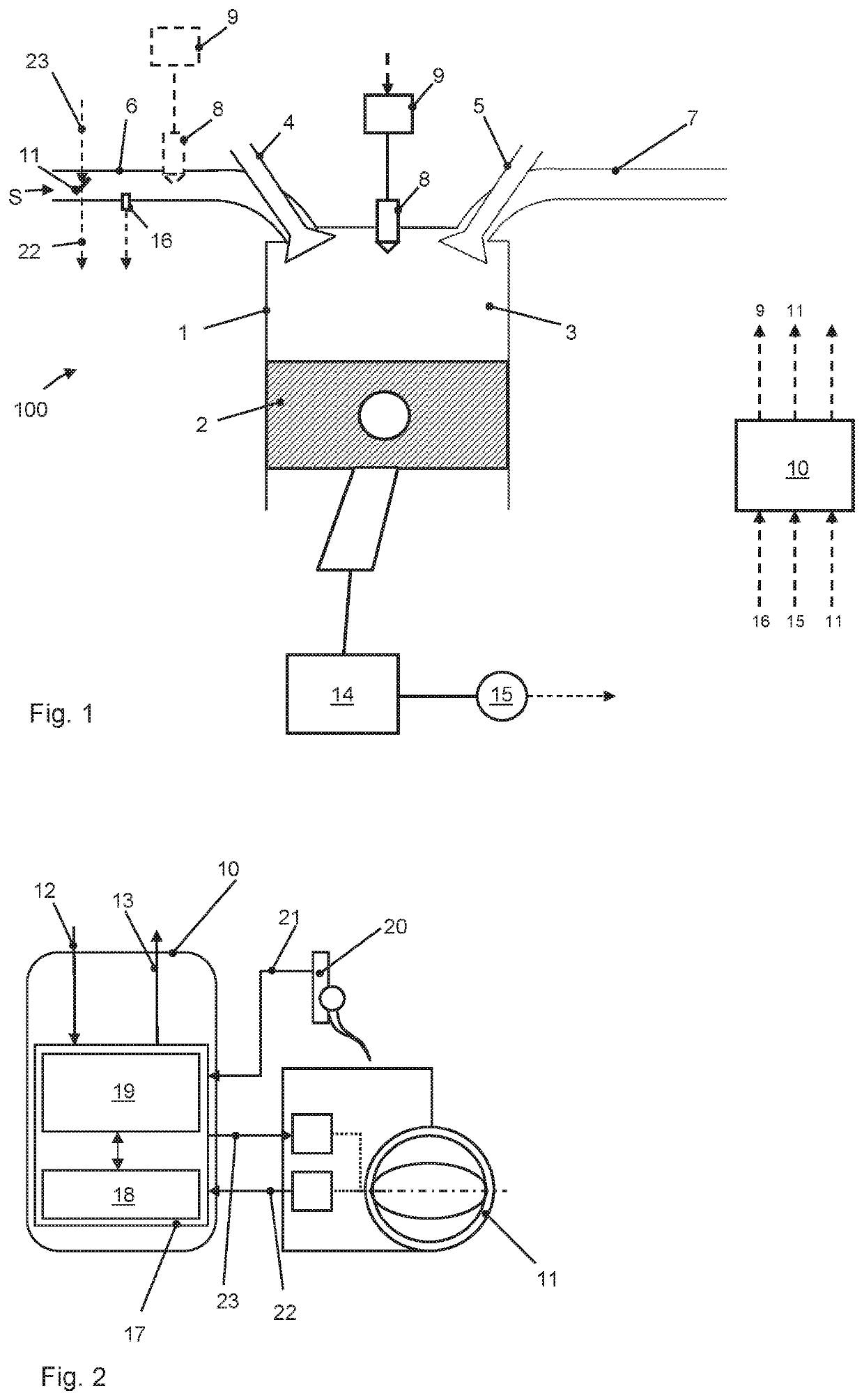
[0045]FIG. 1 schematically shows an internal combustion engine 100 having internal mixture formation (direct injection) and, alternatively, external mixture formation (manifold injection, dashed line representation). Shown is one of a plurality of cylinders 1 having piston 2 that define combustion chamber 3. Combustion chamber 3 is optionally sealed by an intake valve 4 or an exhaust valve 5 or communicates with intake manifold 6 or with exhaust pipe 7.

[0046]Fuel injection motor 8, which is actuated by an actuating element 9 and injects fuel directly into the combustion chamber, leads into combustion chamber 3. For that purpose, actuating element 9 receives control signals from an engine management 10.

[0047]Optionally, fuel injection motor 8, together with actuating element 9, may also lead into intake manifold 6 (dashed line representation). It is then a question of an engine 100 having external mixture formation and manifold injection.

[0048]Configured in intake manifold 6 is throt...


PUM


Abstract

A method for determining an air volume in a combustion chamber of a fuel-injection internal combustion engine, especially during a load change condition, including synchronizing a throttle valve setpoint signal to an operating state criterion (tn); determining a curve dynamics of the throttle valve position taking into account the synchronized throttle valve setpoint signal; determining an actual air volume quantity at an ACTUAL time point (t0); determining a desired time point (t0+Δt); predicting a further air volume quantity for the desired time point (t0+Δt) and determining a total air volume quantity from the ACTUAL air volume quantity and the further air volume quantity for the desired time point (t0+Δt).

Description

CROSS-REFERENCE TO RELATED APPLICATIONS[0001]This application claims the benefit of German Patent Application No. 10 2107 105 853.2, filed Mar. 17, 2017, which is herein incorporated by reference in its entirety.FIELD OF THE INVENTION[0002]The present invention relates to a method for determining an air volume in a combustion chamber of an internal combustion engine, especially a direct-injection spark ignition engine. The present invention also relates to an internal combustion engine having a control that is adapted for implementing such a method. The present invention also relates to a vehicle having such an internal combustion engine.BACKGROUND OF THE INVENTION[0003]In internal combustion engines and especially spark ignition engines, the fuel quantity supplied for combustion is adjusted as a function of an inducted air mass (air volume). The supplied air volume is controlled by what is commonly known as the throttle valve, which is controlled directly or via a control as a func...

Claims


Application Information

Patent Timeline
Patent Type & Authority Patents(United States)
IPC IPC(8): G01M15/04F02D33/02G01F22/02G01M15/05
CPCG01F22/02F02D33/02G01M15/05F02D41/18F02D2200/0402F02D41/009F02D41/1438F02D41/0002F02D2041/1412F02D2041/1433F02D2200/0404F02D2200/0406F02D2200/0408F02D2200/602Y02T10/40
Inventor HEINKEN, SEBASTIANPANKRATZ, KIRSTENPETERSEN, LARSSHURKEWITSCH, ANDRE
Owner VOLKSWAGEN AG
Why Eureka
Try Eureka