Solar collector and method for manufacturing such a solar collector

a solar collector and solar collector technology, applied in the field of solar collectors, can solve the problems of frame deformation, increased distance between the cover and the absorber element, and increased danger, so as to achieve the effect of simplifying and accelerating the final assembly of the solar collector

Inactive Publication Date: 2015-06-16
FATH GMBH
View PDF73 Cites 0 Cited by
  • Summary
  • Abstract
  • Description
  • Claims
  • Application Information

AI Technical Summary

Benefits of technology

[0009]The cover and / or the back wall can comprise a glass, in particular a heat-insulating glass. In this way, a kind of insulating glass composite or insulating glass element is provided that comprises a central absorber. Here, the advantages cited in connection with the spacer element are especially effective. In particular, by the spacer element it is achieved that the solar collector can be produced by standard profiles, whereby the production costs are reduced. Furthermore, the absorber can be arranged freely within the standard profile and thus has sufficient freedom of movement in the case of change in dimensions caused by heat. Overall, the spacer elements allow a simple and economical assembly of the solar collector, especially the insulating glass element with integrated thermal solar collector. The spacer elements also allow an assembly and / or the use or utilization of the solar collector in an inclined position or horizontally on a table.
[0011]In general, the spacer element preferably has a softener-free plastic. The plastic is expediently stable for temperatures occurring in the solar collector. For this purpose, the plastic can have glass fiber admixtures, which increase the stiffness of the collector very generally, in particular also for the case of stagnation. Instead of such a thermoplastic material, duroplastic materials or ceramic materials can also be used.
[0015]Preferably, the spacer element comprises at least one clamping means or tensioning means, which defines the mounting region. The clamping means or tensioning means allows a simple and quick connection of the spacer element to the absorber. For example, the clamping means can have a snap connection-like construction. The clamping means can be clamped with the absorber, for example for mounting, and can form a barbed hook-like locking device. The tensioning means can comprise, for example, a threaded nut that interacts with a fixing element, such that the absorber can be clamped between the fixing element and the nut.
[0019]The spacer element is preferably bonded and / or fused and / or screwed and / or press-bonded to the absorber. Other connection types are also possible. In general, it is advantageous if the spacer element is connected to the absorber, such that the absorber forms one unit with the spacer element or with the several spacer elements. Such an absorber unit can be provided, for example, in a prefabricated manner, so that the final assembly of the solar collector is simplified and accelerated.

Problems solved by technology

Through the absorption of thermal radiation, the absorber element can expand, wherein, in the case of the known solar collector, the danger arises that the frame will deform.
The risk further arises that the distance between the cover and the absorber element increases at least in some areas due to the heating, wherein unfavorable thermal convection and thus reduced efficiency are promoted.

Method used


Image

  • Solar collector and method for manufacturing such a solar collector
  • Solar collector and method for manufacturing such a solar collector
  • Solar collector and method for manufacturing such a solar collector

Examples


Embodiment Construction

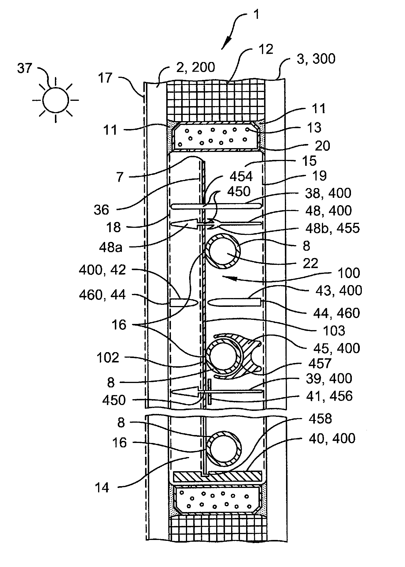
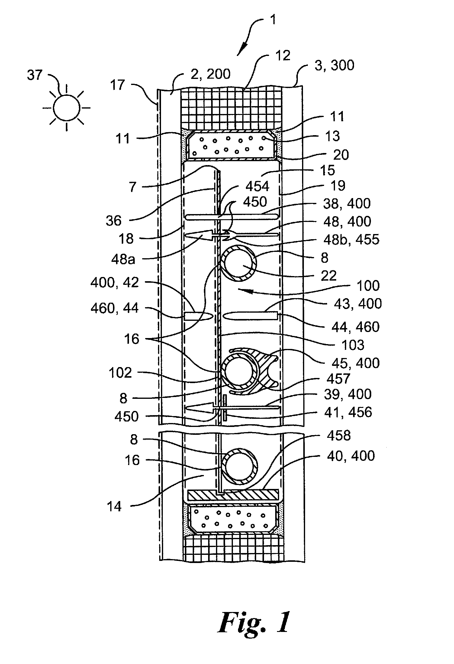
[0030]In FIG. 1 the cross-sectional configuration of a solar collector 1 according to the invention is shown according to a preferred embodiment. The solar collector 1 comprises a front cover 200 and a back wall 300, which are arranged spaced apart from each other. Between the cover 200 and the back wall 300 there is an absorber 7, 8, which comprises an absorber sheet 7 connected rigidly to an absorber tube 8. Between the absorber sheet 7 and the cover 2 there is a front cavity 14. A back cavity 15 is provided between the absorber sheet 7 and the back wall 300. The cavities 14, are each sealed gas-tight relative to the surroundings. For this purpose it is provided, in particular, that at least one spacer element 400 is arranged between the absorber 7, 8 and the cover 200 or the back wall 300.

[0031]In the edge region of the solar collector 1, a hollow profile 20 is arranged between the cover 200 and the back wall 300, with this hollow profile being connected by a primary bonding agen...


PUM

PropertyMeasurementUnit
lengthaaaaaaaaaa
transparentaaaaaaaaaa
distanceaaaaaaaaaa

Abstract

A solar collector (1) is provided having a cover (200), a back wall (300), and an absorber (100), the absorber being arranged between the cover (200) and the back wall (300) and defining, with the cover (200) and / or the back wall (300), a front and / or back cavity (14, 15), respectively. At least one spacer element (400) is provided, which extends from a front surface (102) of the absorber (100) to the cover (200) and / or from a back surface (103) of the absorber (100) to the back wall (300) and is connected or connectable directly to the absorber (100) and / or the cover (200). A method for manufacturing such a solar collector (1) is also provided.

Description

BACKGROUND OF THE INVENTION[0001]The invention relates to a solar collector and also to a method for manufacturing such a solar collector.[0002]From the prior art, solar collectors are known, which comprise a back wall, a surrounding collector frame, an absorber element, and a cover, wherein the absorber element is arranged between the back wall and the cover. Such a solar collector is described, for example, in German Patent DE 10 2006 006 718 B4. In the case of the known solar collector, the cover is constructed as a transparent pane and bonded with the collector frame, which connects the cover to the back wall and the absorber. Here, the cover is arranged spaced apart from the absorber.[0003]In the case of the known solar collector, the absorber element is connected directly to the collector frame. Through the absorption of thermal radiation, the absorber element can expand, wherein, in the case of the known solar collector, the danger arises that the frame will deform. The risk ...

Claims


Application Information

Patent Timeline
Patent Type & Authority Patents(United States)
IPC IPC(8): F24J2/52F24J2/46F24J2/26F24J2/50F24S10/40F24S10/75
CPCF24J2/4636F24J2/268F24J2/4612F24J2/505F24J2/507Y10T29/49355Y02B10/20Y02E10/44F24S2025/601F24S10/755F24S40/40F24S40/80F24S80/52F24S80/54F24S80/58F24S80/56
Inventor ROSTAMI, BARDIAUELZEN, THORSTENKRUSE, JANSCHALLER, WOLFGANG
Owner FATH GMBH
Why Eureka
Try Eureka