Sealing device for large rolling bearing and wind-driven generation device

A rolling bearing, a large-scale technology, applied in the direction of rolling contact bearings, engine sealing, wind power generation, etc., can solve the problem that the metal wire can not perfectly improve the sealing effect, etc.

Inactive Publication Date: 2017-11-10
IMO HOLDING GMBH
View PDF4 Cites 0 Cited by
  • Summary
  • Abstract
  • Description
  • Claims
  • Application Information

AI Technical Summary

Problems solved by technology

But in this case the tensioning wire did not perfectly improve the seal

Method used


Image

  • Sealing device for large rolling bearing and wind-driven generation device
  • Sealing device for large rolling bearing and wind-driven generation device
  • Sealing device for large rolling bearing and wind-driven generation device

Examples


Embodiment Construction

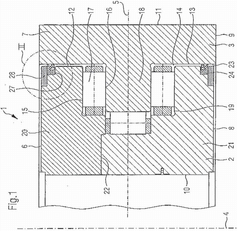
[0078] The drawing shows a rotary bearing 1 with two annular coupling elements 2 , 3 which are arranged radially one above the other. In the center of the two coupling elements 2 , 3 there is a bearing axis of rotation 4 , about which the two coupling elements 2 , 3 can rotate relative to each other. The bearing axis of rotation 4 runs at right angles through the base surface 5 of the rotary bearing 1 , which extends approximately centrally between the flat end sides 6 , 7 , 8 , 9 of the coupling elements 2 , 3 .

[0079] Fastening bores for fastening the two coupling elements 2 , 3 by means of screws or bolts to a respective coupling structure, for example to a machine part or plant part or the like, are not shown. For this purpose, on each coupling element 2 , 3 , a plurality of blind holes are provided in the flat end faces 6 , 7 , 8 , 9 of the coupling elements 2 , 3 in a circular distribution around the bearing axis of rotation 4 . It preferably has an internal thread fo...


PUM


Abstract

The invention relates to a sealing device for a large rolling bearing and a wind-driven generation device. A rotation support mechanism for the large rolling bearing has annular connection members; the annular connection members can rotate relative to each other; the rotation support mechanism has a bearing gap which is sealed by a sealing device on an annular opening; the sealing device has a moulding part; the moulding part has a groove side wing and a groove-shaped recess, the boundary of which is defined by the groove bottom; the depth of the recess is extended and is in parallel with a bearing rotation axis; the groove side wing forms inner sides of two arms of a cross section of the sealing device; one arm is used for archoring the sealing device on the annular connection member; a sealing lip is arranged on the outer side of the other arm; a spring member is inserted into the groove-shaped recess; the spring member is attached against the groove side wing to push away the groove side wing, so that the two arms of the sealing device are spreaded open in the bearing gap between the two conenction members; and thus the sealing lip receives bigger pressure from the outer side of one arm.

Description

technical field [0001] The invention relates to a rotational bearing in the form of a large rolling bearing with at least two annular coupling elements for coupling a stationary or rotating machine part or plant part in each case, wherein the associated The contact of the stationary, stationary or rotating machine parts or plant parts is not done via the curved peripheral sides of the relevant coupling elements (2, 3), but via the flat end sides (6, 7) of the same coupling elements , 8, 9), combined with screws or bolts, the screws or bolts protrude into or extend through the annularly distributed drilling action in the relevant coupling element (2, 3), so that the side of the coupling end (6, 7, 8 , 9) Press firmly and frictionally (reibschlüssig) against the coupling structure, wherein the coupling elements (2, 3) can rotate relative to each other around a common bearing rotation axis, which runs perpendicularly through each annular Base surface of the coupling element, the...

Claims


Application Information

Patent Timeline
Patent Type & Authority Applications(China)
IPC IPC(8): F16J15/3212F16C33/78F03D80/70
CPCF03D80/70F16C33/7816F16C2360/31F16J15/3212F16C19/188F16C33/7823F16C33/7889Y02E10/72
Inventor 亨里克·阿尔伯岑恩亚历山大·彼得
Owner IMO HOLDING GMBH
Why Eureka
Try Eureka