Twin-worm drive swing driving device

A technology of rotary drive and double worm, which is applied in the direction of transmission, transmission parts, gear transmission, etc., can solve the problems of excessive worm clearance, inaccurate positioning, easy damage and failure, etc., and achieves convenient maintenance, simple installation and good structure simple effect

Inactive Publication Date: 2013-08-14
江阴凯迈机械有限公司
View PDF4 Cites 3 Cited by
  • Summary
  • Abstract
  • Description
  • Claims
  • Application Information

AI Technical Summary

Problems solved by technology

[0005] The purpose of the present invention is to solve the technical problems of the worm wheel and the worm clearance that are too large, inaccurate positioning, and easy damage and failure in the single worm drive rotary drive device. Therefore, the present invention proposes a double worm drive rotary drive device

Method used


Image

  • Twin-worm drive swing driving device
  • Twin-worm drive swing driving device
  • Twin-worm drive swing driving device

Examples


Embodiment Construction

[0018] How to implement the present invention will be described below in conjunction with the accompanying drawings.

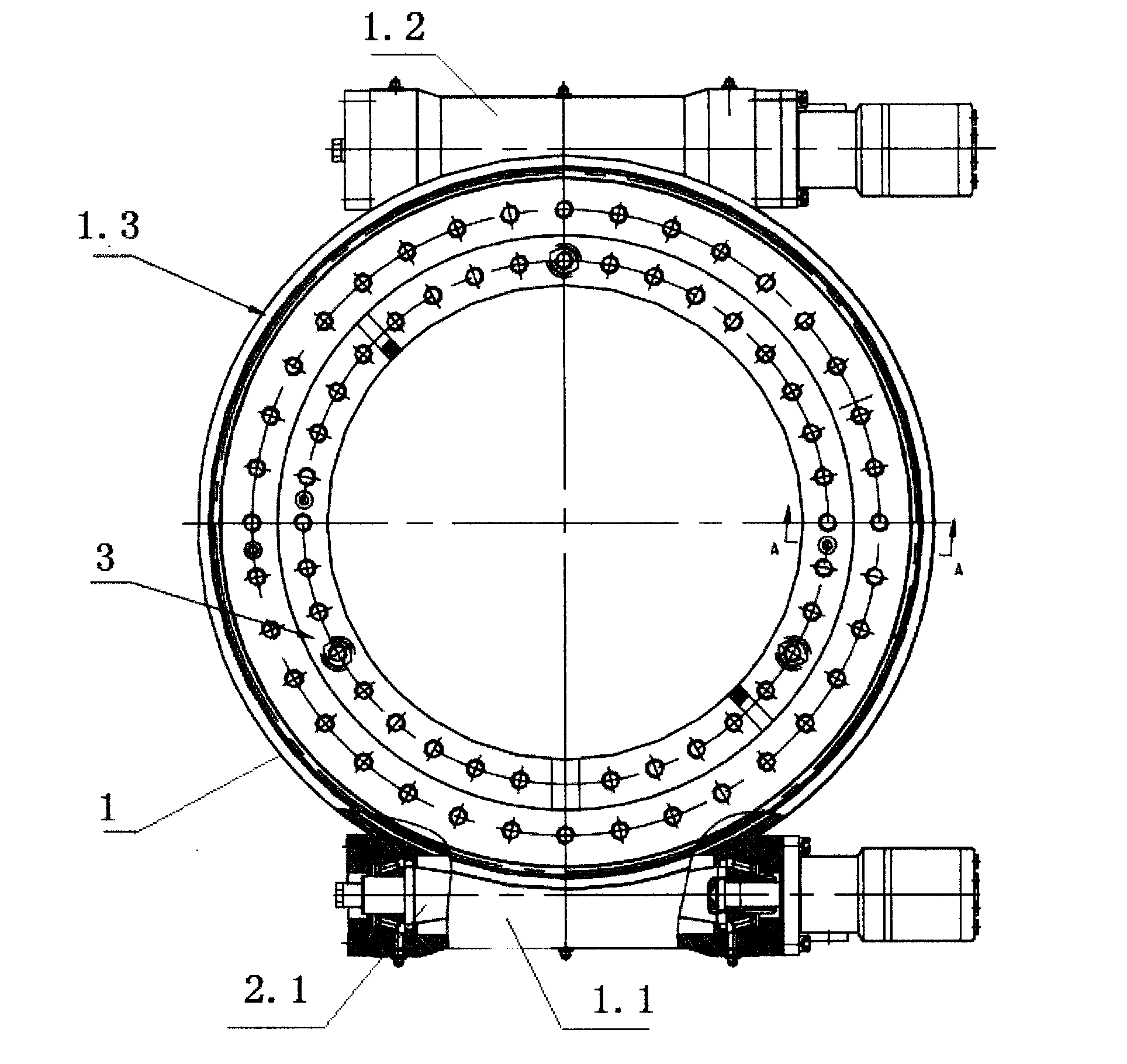
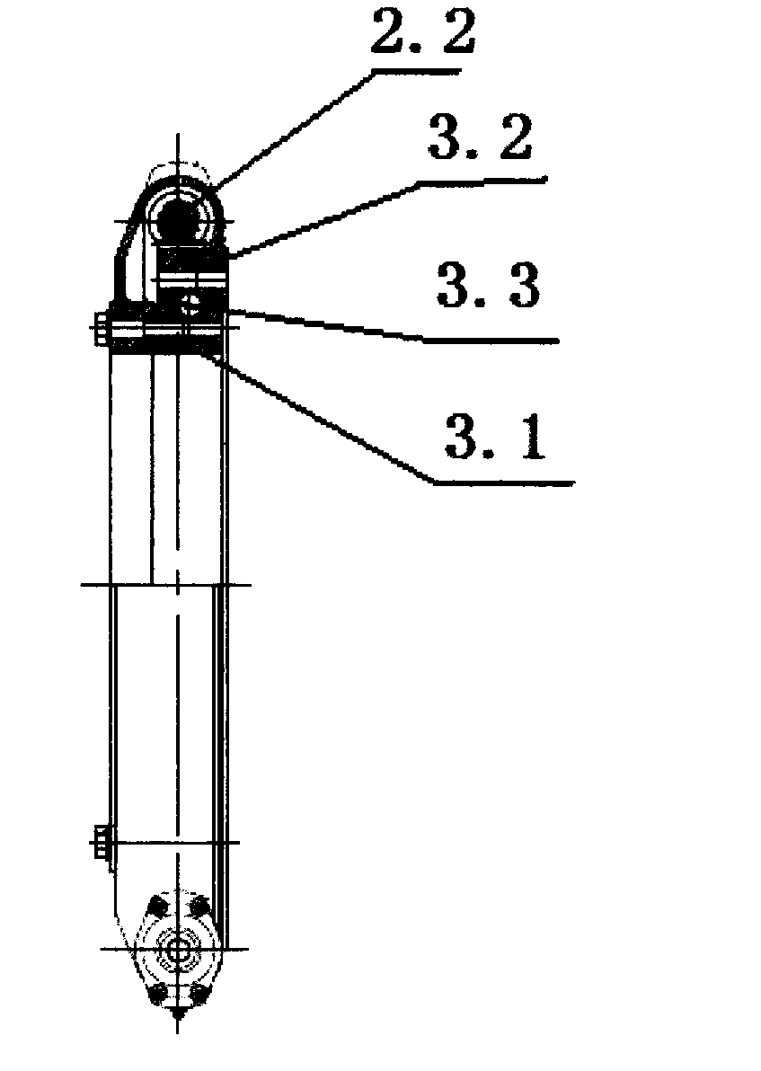
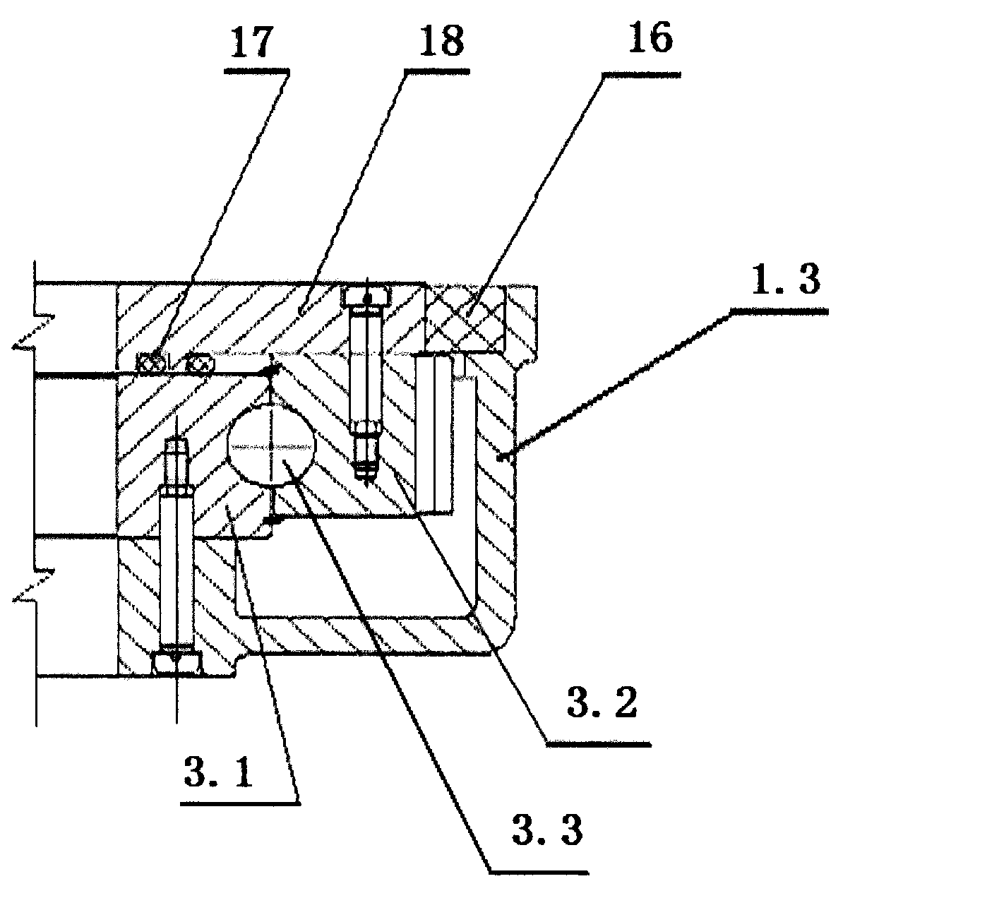
[0019] like figure 1 , 2 , 3, the double worm drive slewing drive device of the present invention can be implemented in the following manner, including a base 1, a slewing support 3, and the slewing support 3 includes an inner ring 3.1, an outer ring gear 3.2 and embedded in the inner ring 3.1 and The balls 3.3 between the outer ring gear 3.2, the outer ring gear 3.2 are provided with several mounting screw holes, the inner ring 3.1 is fixed above the seat ring 1.3 of the base 1, and the outer ring 1.3 of the base 1 is also provided with a second A shaft housing 1.1 and a second shaft housing 1.2, the axis lines of the first shaft housing 1.1 and the second shaft housing 1.2 and the axis line of the seat ring 1.3 are perpendicular to each other in space, and the first shaft housing 1.1 is installed with The first worm 2.1, the second shaft housing 1.2 is ins...


PUM


Abstract

The invention discloses a twin-worm drive swing driving device which comprises a base and a swing bearing. The swing bearing comprises an inner ring, an outer gear ring and balls, the balls are embedded between the inner ring and the outer gear ring, the inner ring is fixed above a base ring of a base, a first shaft housing and a second shaft housing are symmetrically arranged on the outer side of the base ring of the base, the axis lines of the first shaft housing and the second shaft housing are spatially perpendicular to the axis line of the base ring, a first worm is mounted in the first shaft housing, a second worm is mounted in the second shaft housing, and both the first worm and the second worm are engaged with the outer gear ring. The two worms are used for driving the outer gear ring of the swing bearing, translational acting force of the two worms on the outer gear ring is mutually offset, the gap between each worm and the outer gear ring is 'eliminated', and the rotation angle of the outer gear ring is accurately positioned. The twin-worm drive swing driving device is simple in structure and reasonable in design, and can be widely applied to industries such as engineering machinery, building machinery and solar photovoltaics.

Description

technical field [0001] The invention relates to a rotary driving device, in particular to a driving mechanism of the rotary driving device. Background technique [0002] The slewing drive is a component widely used in solar photovoltaics, engineering machinery, and construction machinery. The basic structure of the slewing drive is a worm gear-worm transmission structure. Usually, there are teeth on the outer ring of the slewing bearing, also known as the outer ring gear, which acts as a worm wheel, and then the worm drives the outer ring gear to rotate. [0003] The slew drive is usually provided with a worm to drive the outer ring gear, and this slew drive can be called a single worm drive slew drive. The single worm drive rotary drive device has the advantages of simple structure, low cost, etc., and is widely used. For example, in a solar photovoltaic power generation system, a single worm drive rotary drive is generally used to track the sun's orientation, so that the...

Claims


Application Information

Patent Timeline
IPC IPC(8): F16H1/20F16H57/023F16H57/031
Inventor 周志坚陶连跃汪建生张鑫
Owner 江阴凯迈机械有限公司
Why Eureka
Try Eureka