
Double-wedge-shaped hydraulic chuck for drilling machine

A hydraulic chuck and double-wedge technology, which is applied in the direction of drill pipe, drill pipe, drilling equipment, etc., can solve the problems of large space size of power pump and chuck, increase of system pressure, increase of action area, etc., and achieve novel and reasonable structure, The effect of small radial dimension and large clamping force

Inactive Publication Date: 2014-08-27
CHENGDU UNIVERSITY OF TECHNOLOGY
View PDF0 Cites 2 Cited by
  • Summary
  • Abstract
  • Description
  • Claims
  • Application Information

AI Technical Summary

Problems solved by technology

[0002] In recent years, with the increase of the drilling depth and hole diameter of drilling rigs, the problems existing in traditional chucks have been gradually exposed. Due to the increase in power of drilling rigs, the torque to be transmitted by chucks has also increased, requiring large clamping force and clamping force. Tight and reliable, under the frequent clamping action of the existing spring clamping chuck structure, the life of the spring will be greatly shortened, resulting in a short life of the chuck, and the spring clamping chuck is bulky, so the hydraulic clamping method becomes The development direction of hydraulic chuck
The clamping force of the hydraulic chuck is equal to the product of the system pressure and the area of ​​the hydraulic oil acting surface. Simply increasing the system pressure or increasing the acting area will not only increase the cost, but also reduce the safety, and make the space between the power pump and the chuck larger, resulting in Rig weight and bulk

Method used


Image

  • Double-wedge-shaped hydraulic chuck for drilling machine
  • Double-wedge-shaped hydraulic chuck for drilling machine
  • Double-wedge-shaped hydraulic chuck for drilling machine

Examples


Embodiment Construction

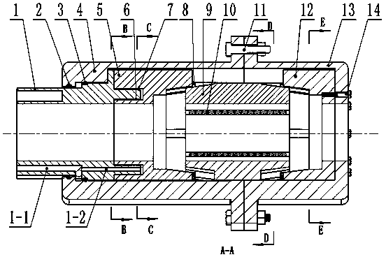
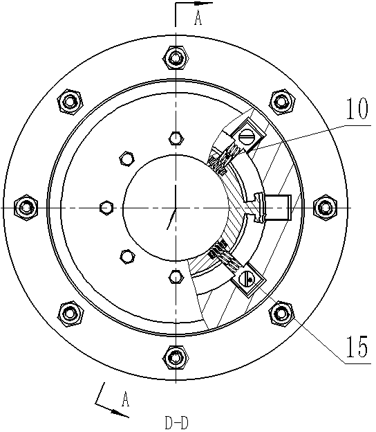
[0014] Combine below figure 1 , figure 2 , image 3 , Figure 4 , Figure 5 and Image 6 The present invention is further described.

[0015] Below in conjunction with accompanying drawing, the present invention is described in further detail:

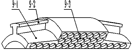
[0016] The present invention is composed of inner cylinder body (1), inner cylinder body sealing ring A (2), inner cylinder body sealing ring B (3), rear outer cylinder body (4), rear ring sleeve (5), inner cylinder body- Small seal ring for ring sleeve (6), large seal ring for inner cylinder body-ring sleeve (7), buffer gasket (8), 4 double wedge slips (9), spring group (10), connecting bolts for outer cylinder body Group (11), front ring sleeve (12), front outer cylinder body (13), front cylinder body-front ring sleeve connecting screw group (14) and buffer washer locking screw group (15).

[0017] The inner cylinder body (1) is connected with the main shaft of the rotary device of the drilling rig or the main shaft connector...


PUM


Abstract

The invention relates to a hydraulic chuck for a drilling machine, in particular to a double-wedge-shaped hydraulic chuck for a drilling machine. The double-wedge-shaped hydraulic chuck for the drilling machine is applied to the drilling machine for tightly clamping a drill rod arranged on a rotating device, transmitting the torque to the drill rod and realizing the rotating movement of a drilling tool. The double-wedge-shaped hydraulic chuck comprises an inner cylinder body, an inner cylinder body sealing ring, a back outer cylinder body, a back ring sleeve, an inner cylinder body-ring sleeve sealing ring, a buffer gasket, double-wedge-shaped slips, a spring group, an outer cylinder body connecting screw bolt group, a front ring sleeve, a front outer cylinder body, a front cylinder body-front ring sleeve connecting screw group and a buffer gasket locking screw group. The double-wedge-shaped hydraulic chuck for the drilling machine has the advantages that the double-wedge-shaped slip clamping is realized through the pressure of hydraulic oil, the double-wedge-shaped slip releasing is realized through the spring reset force, the structure is novel and reasonable, the double-wedge-shaped hydraulic chuck is of a double-wedge-shaped slip structure, two-way clamping is adopted, the clamping force is great, the clamping is fast, the structural dimension is small, and in addition, the axial stress is zero; after the drill rod is released, the chuck is released only through the spring reset force; an oil path of the double-wedge-shaped slip structure is a single loop, the structure is simple, and the control is simple and convenient.

Description

technical field [0001] The invention relates to a drilling rig hydraulic chuck, in particular to a drilling rig double wedge hydraulic chuck. Background technique [0002] In recent years, with the increase of the drilling depth and hole diameter of drilling rigs, the problems existing in traditional chucks have been gradually exposed. Due to the increase in power of drilling rigs, the torque to be transmitted by chucks has also increased, requiring large clamping force and clamping force. Tight and reliable, under the frequent clamping action of the existing spring clamping chuck structure, the life of the spring will be greatly shortened, resulting in a short life of the chuck, and the spring clamping chuck is bulky, so the hydraulic clamping method becomes The development direction of hydraulic chuck. The clamping force of the hydraulic chuck is equal to the product of the system pressure and the area of ​​the hydraulic oil acting surface. Simply increasing the system pr...

Claims


Application Information

Patent Timeline
IPC IPC(8): E21B19/10
Inventor 陈光柱宋平蒋承林黄虎唐敏刘旭辉
Owner CHENGDU UNIVERSITY OF TECHNOLOGY
Learn More