Gear cutting machine, end mill and form milling method

一种切削机床、成形铣削的技术,应用在齿轮切削工具、铣刀、带有齿的元件等方向,能够解决长总加工时间等问题,达到加工时间优化、减少磨损现象的效果

Inactive Publication Date: 2012-10-24
LIEBHERR VERZAHNTECHNIK GMBH
View PDF6 Cites 7 Cited by
  • Summary
  • Abstract
  • Description
  • Claims
  • Application Information

AI Technical Summary

Problems solved by technology

In order to avoid local overloading of the tool, the tool speed must therefore be adjusted, which results in a longer overall machining time

Method used


Image

  • Gear cutting machine, end mill and form milling method
  • Gear cutting machine, end mill and form milling method
  • Gear cutting machine, end mill and form milling method

Examples


Embodiment Construction

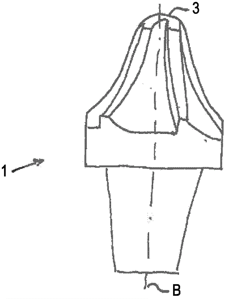
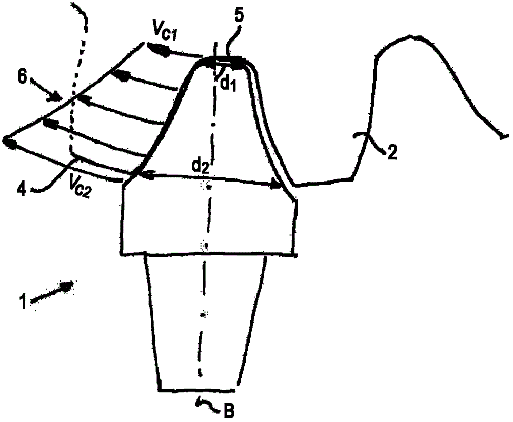
[0027] figure 1 and figure 2 Having already been discussed in the introductory part of the description, details in the views shown will not be discussed again in this part of the description.

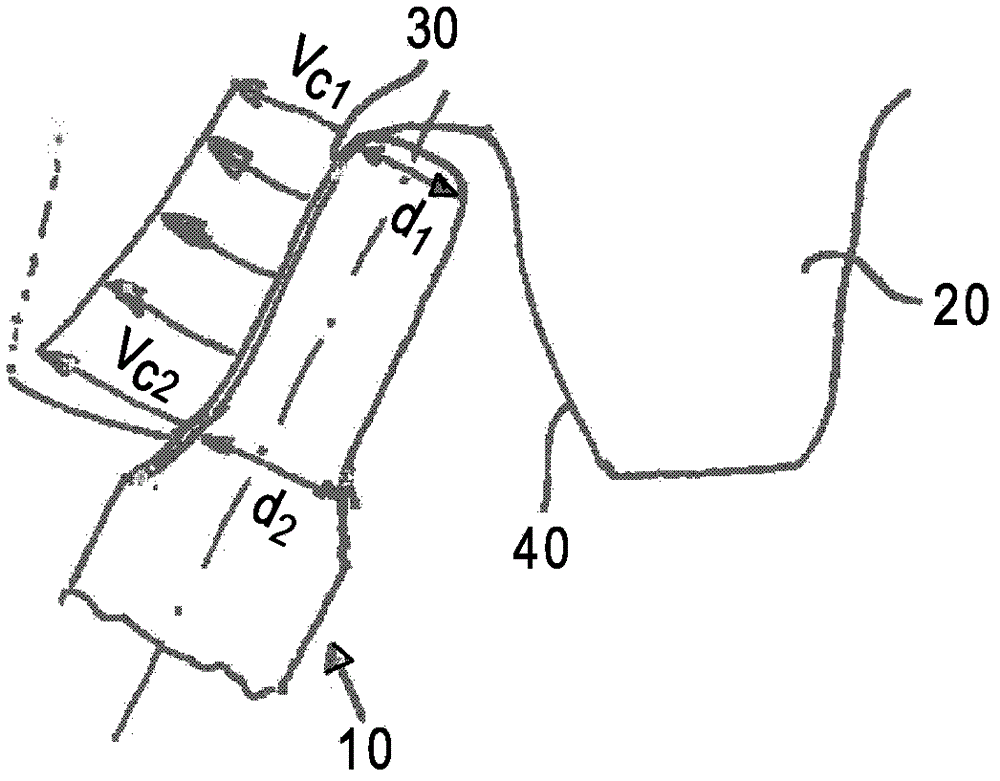
[0028] image 3 A schematic view of an end mill 10 according to the invention is shown, which is cutting a workpiece in the form of a toothed disc 20 with an involute tooth profile. According to the invention, the end mill 10 is mounted on a tool post of a CNC (Computer Numerically Controlled) gear cutting machine and arranged to rotate about a tool axis A. As shown in FIG. The resulting tool speed is designated n and given in revolutions per minute. The machine kinematics aligns the end mill 10 according to the machining of the tooth flanks of the toothed disc 20 . In this respect, either the tool or the tool holder can be moved together with the workpiece or both are combined.

[0029] Figure 4 The machining axis for aligning the end mill 10 is shown. The milling cutter 10 is...


PUM


Abstract

The present invention relates to a gear cutting machine, an end mill and a form milling method. The gear cutting machine performs gear cutting for a workpiece, especially performs gear cutting for a tooth-form wheel disc, through a forming mill having at least one tool rest used for installing at least one end mill, wherein, the tool rest or the end mill and / or workpiece support are adjustable, an axis of the end mill can be arranged into a processing tooth surface approximately parallel to a clamped workpiece, and wherein, an axis of a tool is suitable for a contour of the tooth surface, and the end mill has an outer contour corresponding to the contour of the tooth surface.

Description

technical field [0001] The present invention relates to a gear cutting machine tool for cutting teeth of a workpiece, especially a toothed wheel, by performing form milling with an end mill. Background technique [0002] Tooth milling cutters in the form of end mills are used on gear cutting machines for cutting teeth of toothed discs and milling worm gears depending on the forming method. The use of such end mills starts with eg module 10 toothed discs and extends to the largest cutting tooth sizes. When milling worm gears, these end mills are also used in very small modules to machine worm gears and worm discs. [0003] Tools in the form of end mills or, even better, flank milling cutters are also used to pre-mill large cutting teeth. End mills are preferably used where no other tool can be used, for example because of collisions, such as when machining closed herringbone gears, when machining double helical gears with a small intermediate space, or where there is no sui...

Claims


Application Information

Patent Timeline
Patent Type & Authority Applications(China)
IPC IPC(8): B23F21/12
CPCB23F21/12B23C2210/084B23F1/06B23C5/10B23F21/122Y10T407/1745Y10T409/103816Y10T409/103975Y10T409/10795Y10T409/108109Y10T409/108745
Inventor 阿洛伊斯・蒙特
Owner LIEBHERR VERZAHNTECHNIK GMBH
Why Eureka
Try Eureka