Stator core

a technology of stator core and core, which is applied in the direction of dynamo-electric machines, electrical apparatus, magnetic circuit shapes/forms/construction, etc., can solve the problems of low winding efficiency, limited winding number of turns, and undetectable relative circumferential movement between

Inactive Publication Date: 2015-06-16
JOHNSON ELECTRIC SA
View PDF8 Cites 4 Cited by
  • Summary
  • Abstract
  • Description
  • Claims
  • Application Information

AI Technical Summary

Benefits of technology

[0016]In the embodiments of the present invention, the relative circumferential movement between adjacent yoke portions can be avoided after the external force for bending the bent portions is withdrawn.

Problems solved by technology

It is not convenient to wind windings on a closing structure, so the winding efficiency is low and sometimes the number of turns of the winding is limited.
However, as the arc shaped fitting portions can only prevent relative axial movement between the adjacent yokes, after the external force for bending a bent portion is withdrawn a rebound between the adjacent yokes may occur, which will result in undesired relative circumferential movement between the adjacent yokes.

Method used


Image

  • Stator core
  • Stator core
  • Stator core

Examples


Embodiment Construction

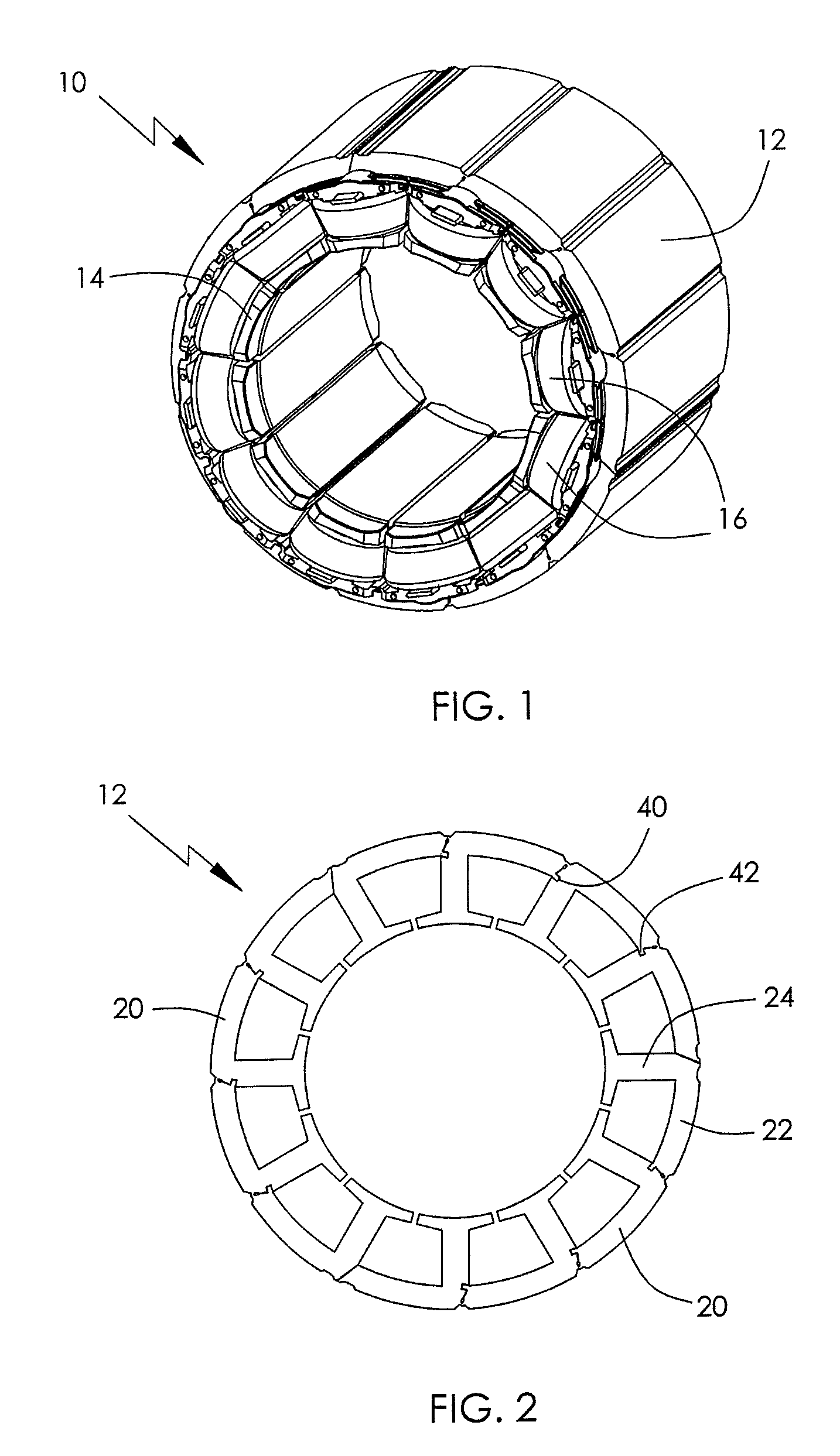
[0025]FIG. 1 illustrates a wound stator 10 of an electric motor, having a stator core 12 in accordance with a preferred embodiment of the present invention. A plurality of insulating bobbins 14 with stator windings 16 wound thereon are sleeved on the stator core 12.

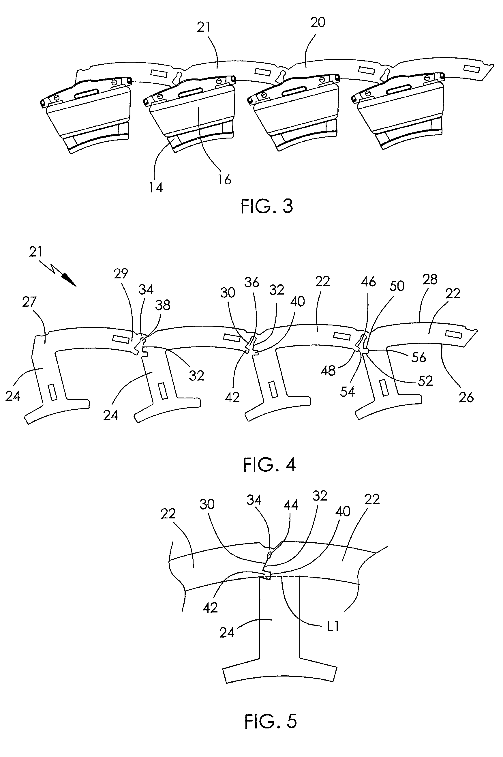
[0026]Referring to FIGS. 2 and 3, the stator core 12 is formed by a plurality of separate bendable strip-shaped cores 20 which are connected end to end in sequence so as to form a circumferential configuration or circle after being bent. The strip-shaped core 20 is formed by stacking a plurality of bendable strip-shaped laminations 21. The stator windings 16 can be formed on the teeth of a strip-shaped core 20 before the strip-core 20 is bent.

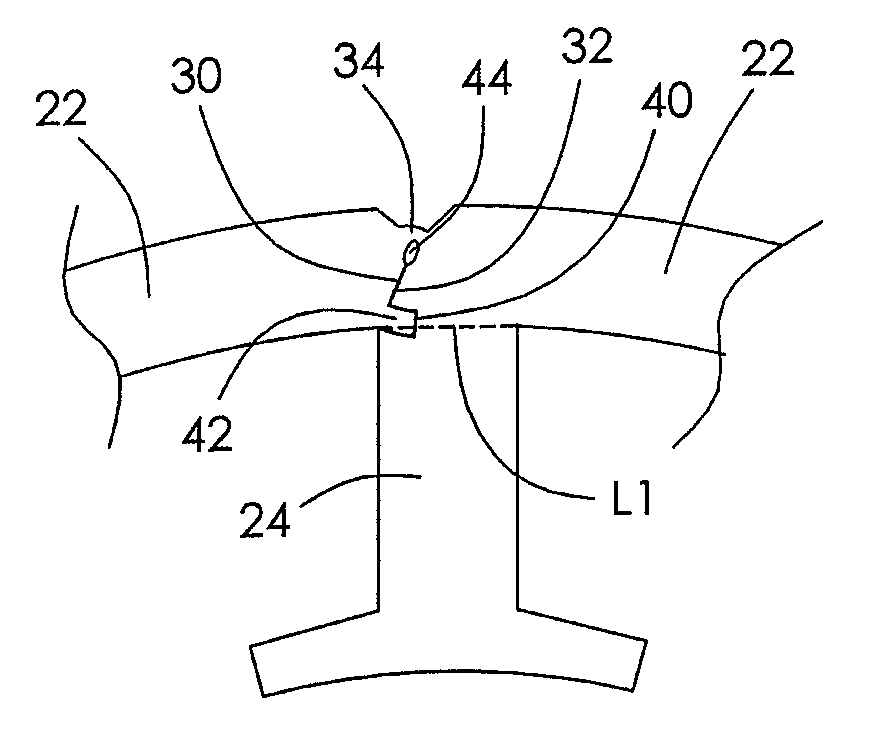
[0027]FIG. 4 illustrates a bendable strip-shaped lamination 21 before being bent. The strip-shaped lamination 21 comprises a plurality of yoke portions 22 and a plurality of tooth portions 24. Each yoke portion 22 has an inner surface 26, an outer surface 28, and first and second end...


PUM


Abstract

A stator core includes at least one bendable strip-shaped core. Each strip-shaped core is formed by stacking a plurality of laminations. Each lamination includes at least two yoke portions and at least two tooth portions. Every two adjacent yoke portions are connected to each other via a bendable portion and have two opposite end surfaces, one of the end surfaces having a groove and the other having a projecting rib. After the bendable portion is bent the projecting rib is engaged in the groove to form an interlock structure such that relative circumferential movement between the adjacent yoke portions is limited.

Description

CROSS REFERENCE TO RELATED APPLICATIONS[0001]This non-provisional patent application claims priority under 35 U.S.C. §119(a) from Patent Application No. 201110283293.5 filed in The People's Republic of China on Sep. 21, 2011.FIELD OF THE INVENTION[0002]This invention relates to a stator core and in particular, to a stator core having a number of strip-shaped cores.BACKGROUND OF THE INVENTION[0003]A typical known stator for a brushless motor comprises a stator core which comprises an annular yoke and a plurality of teeth radially extending from the yoke. Traditionally the stator core is formed by stacking a plurality of stator laminations together and each lamination is a monolithic piece with a closing structure. During production, the stator laminations are stacked together to form the stator core firstly, and then stator windings are wound on the teeth of the stator core. It is not convenient to wind windings on a closing structure, so the winding efficiency is low and sometimes t...

Claims


Application Information

Patent Timeline
Patent Type & Authority Patents(United States)
IPC IPC(8): H02K1/12H02K1/14
CPCH02K1/148H02K2213/03
Inventor LI, YUELIU, BAO TINGLAI, KUI MANWANG, YONGZHU, XIAO NING
Owner JOHNSON ELECTRIC SA
Why Eureka
Try Eureka