Circuit breaker and closing resistor thereof

A technology for closing resistors and circuit breakers, which is applied in the direction of high-voltage air circuit breakers, resistors, resistor installation/support, etc., and can solve problems such as damage to resistor sheets and insulating rods

Pending Publication Date: 2022-05-06
PINGGAO GRP +3
View PDF1 Cites 0 Cited by
  • Summary
  • Abstract
  • Description
  • Claims
  • Application Information

AI Technical Summary

Problems solved by technology

[0005] The purpose of the present invention is to provide a closing resistor of a circuit breaker to solve the problem in the prior art that the resistance sheet and the insulating rod are easily damaged after the resistance sheet and the insulating rod collide with each other due to the rigid contact between the resistance sheet and the insulating rod. Problem; the object of the present invention is also to provide a circuit breaker to solve the technical problem in the prior art that the resistance sheet and the insulation rod are easily damaged after they collide with each other due to the rigid contact between the resistor sheet and the insulation rod

Method used


Image

  • Circuit breaker and closing resistor thereof
  • Circuit breaker and closing resistor thereof
  • Circuit breaker and closing resistor thereof

Examples


Embodiment 1

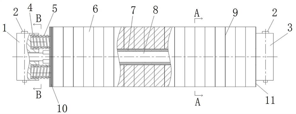
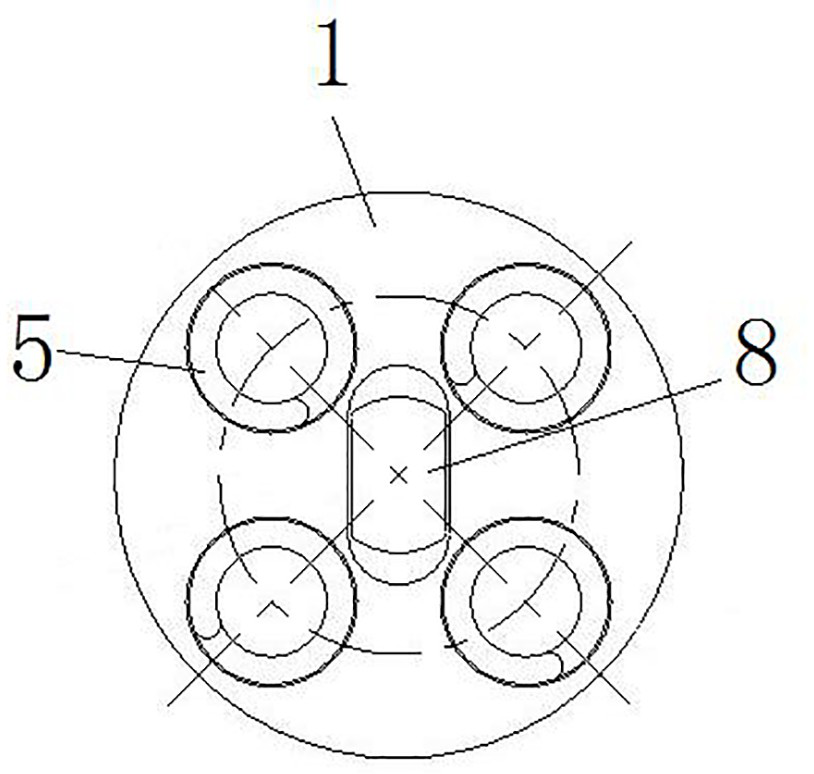
[0061] Such as figure 1 As shown, the closing resistor of the circuit breaker includes an insulating rod 8 extending along the left and right directions. The insulating rod 8 is stacked with a plurality of resistance pieces 6 along its axial direction. The left end of the insulating rod 8 is fixed by the pin shaft 2. There is a left connecting seat 1, and the right end of the insulating rod 8 is fixedly provided with a right connecting seat 3 through a bearing pin 2.

[0062] In this embodiment, the insulating rod 8 is provided with a conductive damping sheet 9 between any two adjacent resistance sheets 6, and the conductive vibration damping sheet 9 is provided with a vibration damping pattern (not shown) to achieve a better damping effect. vibration effect. Wherein, the conductive damping sheet 9 is an aluminum sheet.

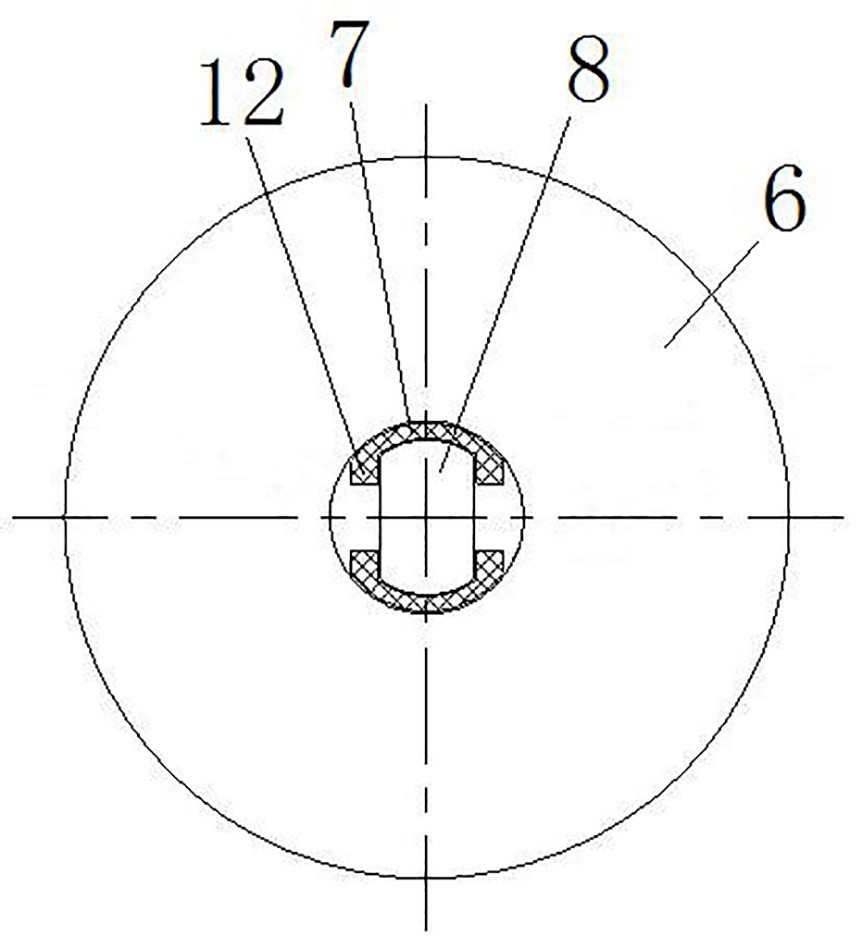
[0063] Such as figure 1 and figure 2 As shown, a buffer is provided between the insulating rod 8 and the resistive sheet 6. When vibrating, the buffer a...

Embodiment 2

[0075] In Embodiment 1, the buffer is a buffer pad 7 arranged between the resistor sheet 6 and the insulating rod 8 , two buffer pads are provided, and the buffer pad 7 plays a buffering role on the resistor sheet 6 and the insulating rod 8 . In this embodiment, the buffer member is a buffer sleeve arranged between the resistor sheet and the insulating rod, one buffer sleeve is provided, and the buffer sleeve acts as a buffer for the resistor sheet and the insulating rod, wherein the buffer sleeve is an annular sleeve. In other embodiments, the buffer sleeve may be a C-shaped sleeve.

Embodiment 3

[0077] In Embodiment 1, two buffer pads 7 are arranged at intervals in the circumferential direction of the insulating rod 8 , which not only facilitates the installation of the buffer pads, but also reduces the cost of manufacturing the buffer pads 7 . In this embodiment, on the basis of setting two buffer pads, the limiting protrusions of the two buffer pads are arranged in abutment with each other, so as to completely wrap the insulating rod.


PUM


Abstract

The invention relates to a circuit breaker and a closing resistor thereof. The closing resistor of the circuit breaker comprises an insulating rod; the plurality of resistor discs are arranged, and all the resistor discs are stacked and sleeved on the insulating rod along the axial direction of the insulating rod; and the buffer piece is arranged between the insulating rod and the resistor disc so as to play a role in buffering the insulating rod and the resistor disc during vibration. According to the utility model, the buffer pad is arranged between the resistor disc and the insulating rod, so that the problem that the resistor disc and the insulating rod collide with each other and are damaged due to vibration generated in the process of transporting and operating the circuit breaker is solved, and the safety and reliability of a product during operation are improved. In addition, the buffer pad is arranged between the resistor disc and the insulating rod, so that the appearance of the insulating rod is not restrained, and diversified design can be carried out on the insulating rod.

Description

technical field [0001] The invention relates to a circuit breaker and its closing resistor. Background technique [0002] In the high-voltage power system, the distributed inductance and distributed capacitance parameters on the grid system are large. When GCB is operated, it will cause an operating overvoltage with a peak value greater than the rated lightning impulse, which is harmful to the grid system. In order to limit the operating overvoltage, it is necessary to set a closing resistor at the GCB fracture to consume the energy of electromagnetic oscillation. [0003] The Chinese patent application with the authorized notification number CN102723154A discloses a resistor, which includes an insulating rod and a resistor sheet. The number of the resistor sheets is multiple and stacked on the insulating rod. The conductive shock absorber on the insulating rod; the two ends of the insulating rod are respectively equipped with left and right connecting seats, wherein, the r...

Claims


Application Information

Patent Timeline
Patent Type & Authority Applications(China)
IPC IPC(8): H01C13/02H01C1/01F16F15/02H01H33/42
CPCH01C13/02H01C1/01F16F15/02H01H33/42
Inventor 骆常璐杨姣龙贺晶晶孙明道高振奎史峰涛张凯李小俊李伟宋辉军孙金奇
Owner PINGGAO GRP
Why Eureka
Try Eureka