TIG welding method and apparatus

a welding method and welding technology, applied in the direction of welding/cutting media/materials, welding apparatus, manufacturing tools, etc., can solve the problems of permanent magnets overheating, inability to obtain a higher aspect ratio weld zone cross-sectional shape,

Active Publication Date: 2015-06-23
DENSO CORP
View PDF25 Cites 0 Cited by
  • Summary
  • Abstract
  • Description
  • Claims
  • Application Information

AI Technical Summary

Benefits of technology

[0007]The present invention was made in consideration of the above situation and has as its object to provide a TIG welding method and apparatus which enable a higher aspect ratio weld zone cross-sectional shape to be obtained and which further can prevent the heat radiated from the weld arc from causing the permanent magnets to overheat.
[0009]By arranging the permanent magnets around the electrode of the welding torch and moving the permanent magnets to make the magnetic field fluctuate, electromotive force is generated and an eddy current is formed. Due to the formation of this eddy current, the Lorentz force of the weld pool increases and a force which drives inward convection increases. Due to such action, a higher aspect ratio weld zone cross-sectional shape can be obtained. Further, due to the movement of the permanent magnets, heat conduction is accelerated between the surrounding air and the permanent magnets and therefore heat radiated from the weld arc can be prevented from causing the permanent magnets to overheat.
[0010]According to a second aspect of the present invention, the TIG welding method makes the permanent magnets (7) move back and forth cyclically in an axial direction of the electrode (4) of the welding torch (3) to thereby cause the magnetic field to fluctuate. This shows one mode of motion of the permanent magnets.
[0012]By arranging the permanent magnets around the electrode of the welding torch and moving the permanent magnets to make the magnetic field fluctuate, electromotive force is generated and an eddy current is formed. Due to the formation of this eddy current, the Lorentz force of the weld pool increases and a force which drives inward convection increases. Due to such action, a higher aspect ratio weld zone cross-sectional shape can be obtained. Further, due to the movement of the permanent magnets, heat conduction is accelerated between the surrounding air and the permanent magnets and therefore heat radiated from the weld arc can be prevented from causing the permanent magnets to overheat.
[0013]According to a fourth aspect of the present invention, the TIG welding apparatus makes the permanent magnets (7) move back and forth cyclically in an axial direction of the electrode (4) of the welding torch (3) to thereby cause the magnetic field to fluctuate. This shows one mode of motion of the permanent magnets.

Problems solved by technology

However, when using the welding method of Japanese Patent Publication (A) No. 2008-105056, it is not possible to obtain a higher aspect ratio weld zone cross-sectional shape.
The “aspect ratio” means the ratio of the melt depth H and average melt width W. Further, as shown in Example 2 of Japanese Patent Publication (A) No. 2008-105056 (FIG. 2), when arranging permanent magnets around the electrode of a welding torch, there is the inconvenience that sometimes the heat radiated from the weld arc causes the permanent magnets to overheat.

Method used


Image

  • TIG welding method and apparatus
  • TIG welding method and apparatus
  • TIG welding method and apparatus

Examples


first embodiment

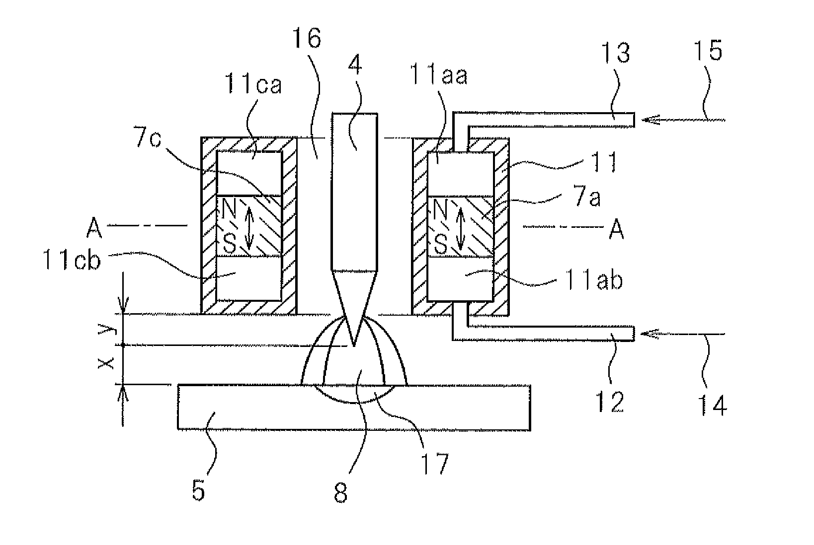
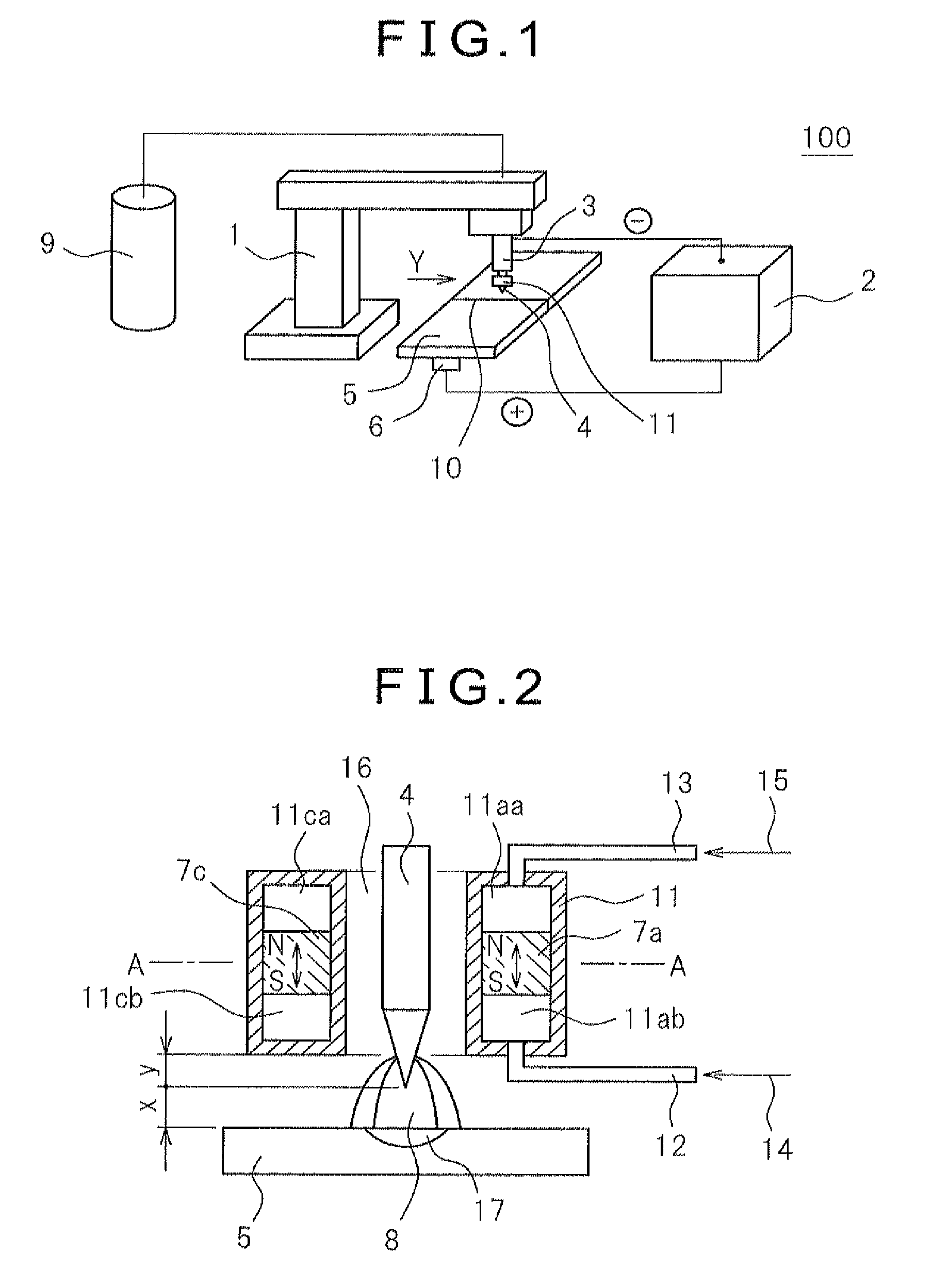
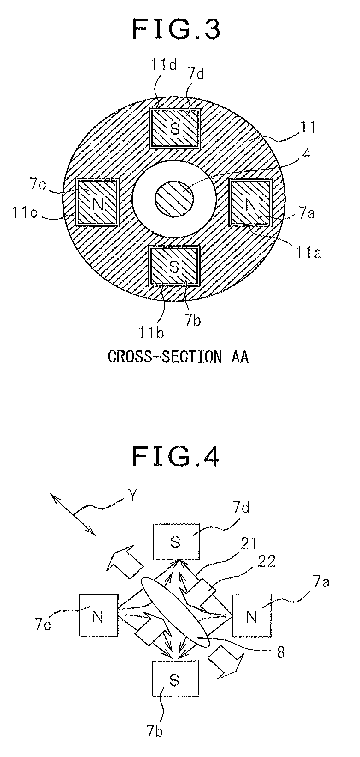
[0022]FIG. 1 is a schematic view of a TIG welding apparatus 100 of the present invention which is provided with permanent magnets 7 which cause the generation of a magnetic field between an electrode 4 and a workpiece 5. As shown in FIG. 1, the TIG welding apparatus 100 is provided with an electrode 4 of a welding torch 3 which is arranged at a welding machine body 1 and to which a negative electrode of a TIG welding power supply 2 is connected and an electrode 6 which is connected to a workpiece 5 and which acts as a positive electrode. Inert gas is supplied from a shielding gas container 9 to an outer circumference 16 of the electrode 4 (see FIG. 2). Further, not shown inert gas is ejected from between the later explained magnet housing 11 and electrode 4, covers the surface of the weld arc 8, and prevents the weld zone from oxidizing. Further, the center axis of the electrode 4 of the welding torch 3 and the welded part 10 of the workpiece 5 (weld line) 10 are made to match. Furt...


PUM

PropertyMeasurementUnit
pressureaaaaaaaaaa
speedaaaaaaaaaa
distanceaaaaaaaaaa

Abstract

A TIG welding method and apparatus which enable a higher aspect ratio weld zone cross-sectional shape to be obtained and which further can prevent the heat radiated from the weld arc causing the permanent magnets to overheat, specifically a TIG welding method which causes an arc discharge between a workpiece and an electrode of a welding torch to cause the generation of a weld arc, uses permanent magnets to generate a magnetic field around the weld arc, and causes an electromagnetic force which is generated by electromagnetic interaction between the magnetic field and a current to act on a weld pool of the workpiece in welding, the TIG welding method arranging the permanent magnets around the electrode of the welding torch and moving the permanent magnets to make the magnetic field fluctuate and thereby make the drive force of convection which is applied to the weld pool fluctuate.

Description

BACKGROUND OF THE INVENTION[0001]1. Field of the Invention[0002]The present invention relates to a TIG welding method and apparatus. More specifically, it relates to a TIG welding method and apparatus which cause an arc discharge between a workpiece and an electrode of a welding torch to cause the generation of a weld arc, use permanent magnets to cause the generation of a magnetic field around the weld arc, and make electromagnetic force which is generated due to electromagnetic interaction of the magnetic field and current act on a weld pool of the workpiece in welding.[0003]2. Description of the Related Art[0004]As a TIG welding method and apparatus which cause an arc discharge between a workpiece and an electrode of a welding torch to cause the generation of a weld arc, use permanent magnets to cause the generation of a magnetic field around the weld arc, and make electromagnetic force which is generated due to electromagnetic interaction of the magnetic field and current act on...

Claims


Application Information

Patent Timeline
Patent Type & Authority Patents(United States)
IPC IPC(8): B23K9/24B23K9/08B23K9/167
CPCB23K9/08B23K9/167
Inventor HAYAKAWA, TSUYOSHISHIRAI, HIDEAKI
Owner DENSO CORP
Why Eureka
Try Eureka