Modular heat-radiation structure and controller including the structure

a heat-radiation structure and controller technology, applied in the direction of electrical apparatus contruction details, lighting and heating apparatuses, printed circuit non-printed electric components association, etc., can solve the problems of difficult to prevent deformation due to thermal expansion of printed circuit boards, and achieve the effects of preventing heat radiation, saving space, and easy formation

Inactive Publication Date: 2010-06-29
MITSUBISHI ELECTRIC CORP
View PDF17 Cites 9 Cited by
  • Summary
  • Abstract
  • Description
  • Claims
  • Application Information

AI Technical Summary

Benefits of technology

[0012]According to the first aspect of the present invention, radiation heat generated from the bottom face of the modular main unit is shielded by the heat shield, and heat generated from the top face of the modular main unit is also conducted to the heat-radiation fin and radiated to outer space thereby. Therefore, it is effective to prevent deformation, etc. of the printed circuit board caused by thermal expansion due to heat generated from the bottom of a module.
[0013]According to the second aspect of the present invention, because either the slit or the concave for inserting the chip is provided as the heat shield, the chip can be installed inside the heat shield. Therefore, it is effective to prevent heat radiated from the modular bottom face, and also to save space.
[0014]According to the third aspect of the present invention, because the separator for separating from the electric power source the heat-radiation fin and the module is provided in the case, radiation heat generated from the heat-radiation fin and the module is shielded by the separator. Therefore, it is effective that the radiation heat generated from the heat-radiation fin and the module is difficult to transmit to the electric power source.
[0015]According to the forth aspect of the present invention, not only the separator can be easily formed, but also because the second separator is approximately U-shaped, radiation heat generated from the module can be shielded by the second separator. Therefore, it is effective that the radiation heat is difficult to transmit to the electric power source.
[0016]According to the fifth aspect of the present invention, because heat generated from the heat-radiation fin can be shielded by the top of the case, heat radiation from the heat-radiation fin to the module is reduced. Therefore, it is effective to accelerate the heat radiation from the module.
[0017]According to the sixth aspect of the present invention, it is effective that not only the heat-radiation fin can be commonly used for the module and the stack, but also the stack can easily be thermally connected to the heat-radiation fin.

Problems solved by technology

However, accompanying high-density mounting inside a controller, in the above modular attachment structure, due to heat generation from the bottom face of the module, a problem has occurred that, for example, deformation due to the thermal expansion of the printed circuit board is difficult to be prevented.

Method used


Image

  • Modular heat-radiation structure and controller including the structure
  • Modular heat-radiation structure and controller including the structure
  • Modular heat-radiation structure and controller including the structure

Examples


embodiment 1

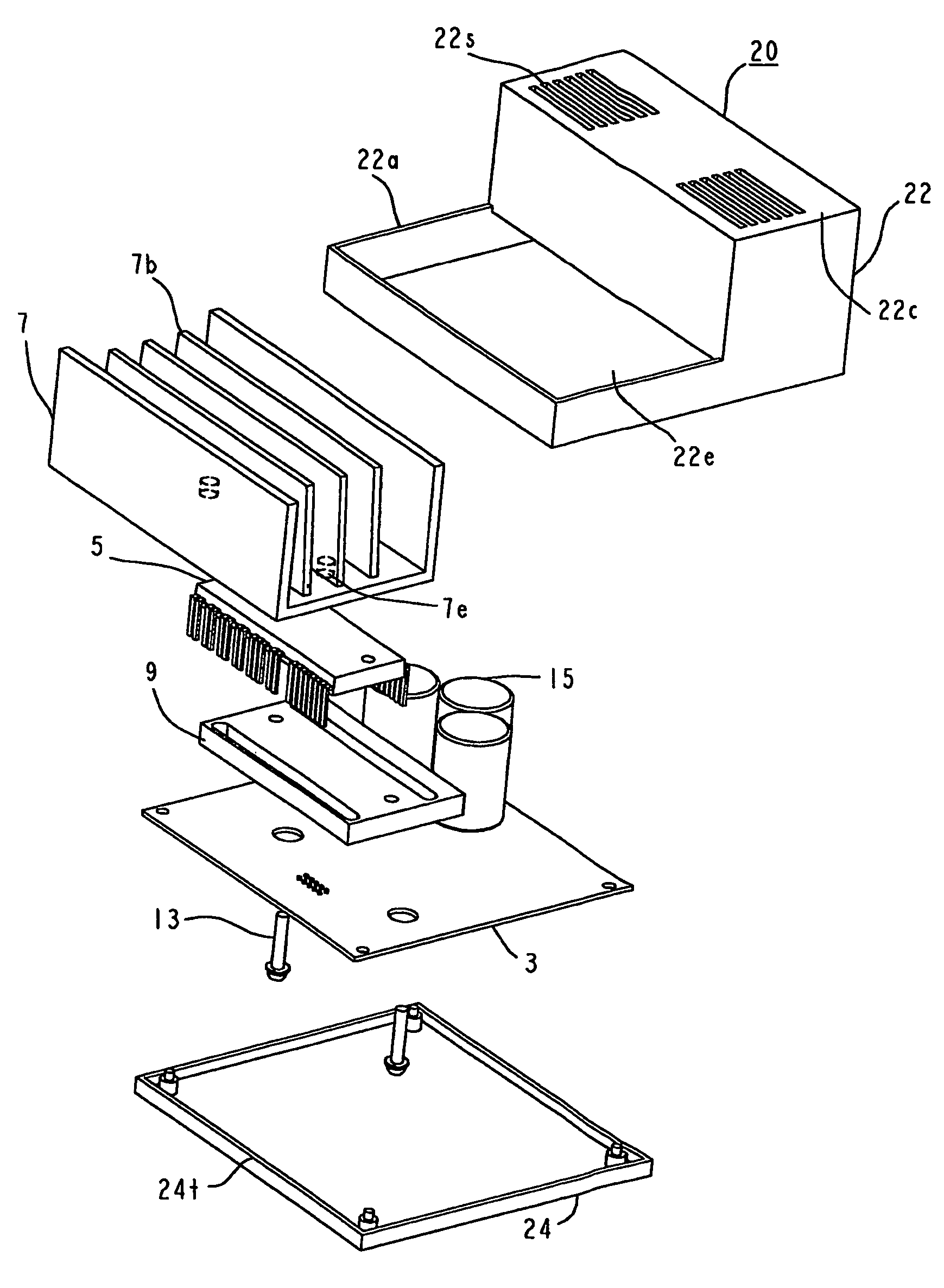
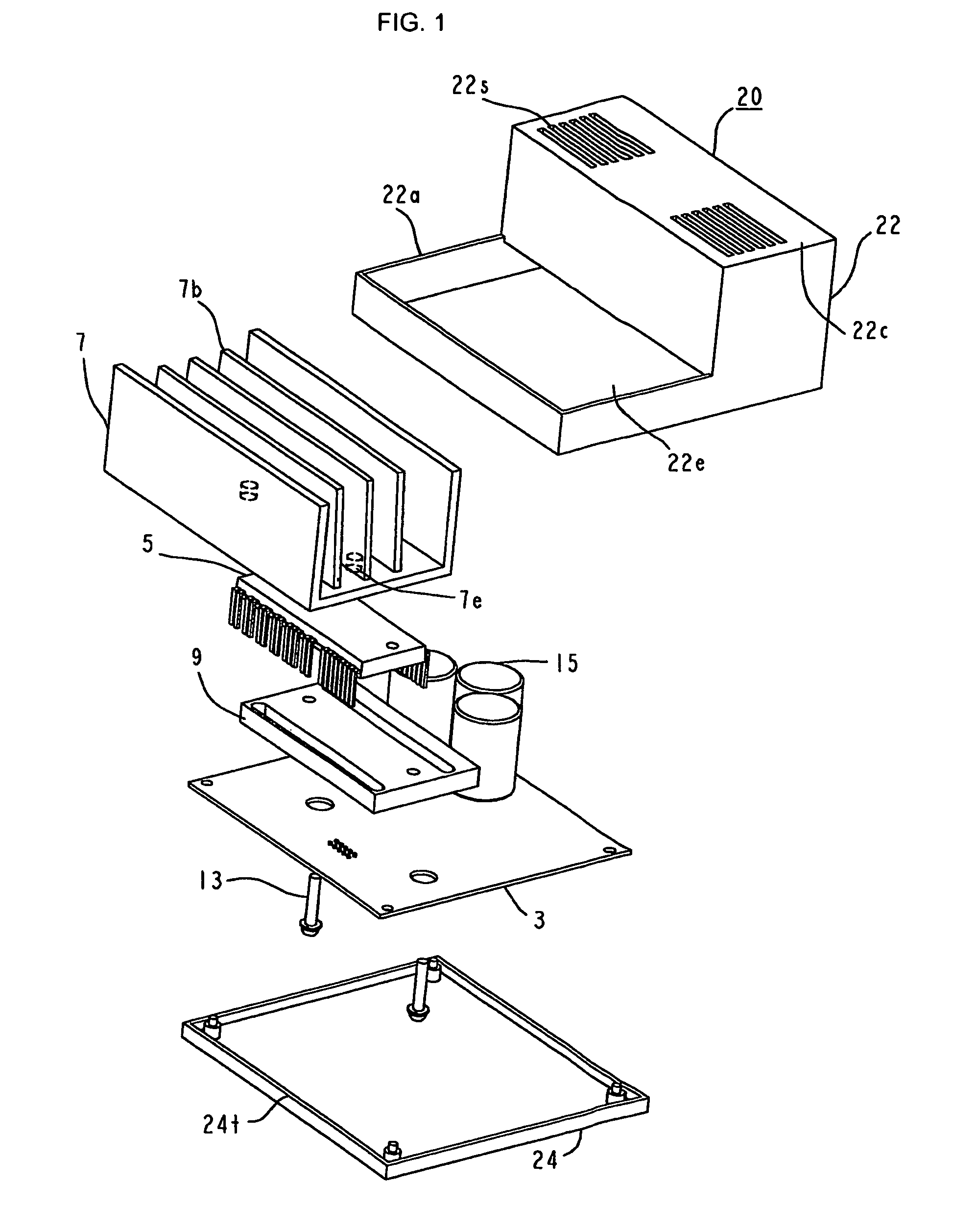
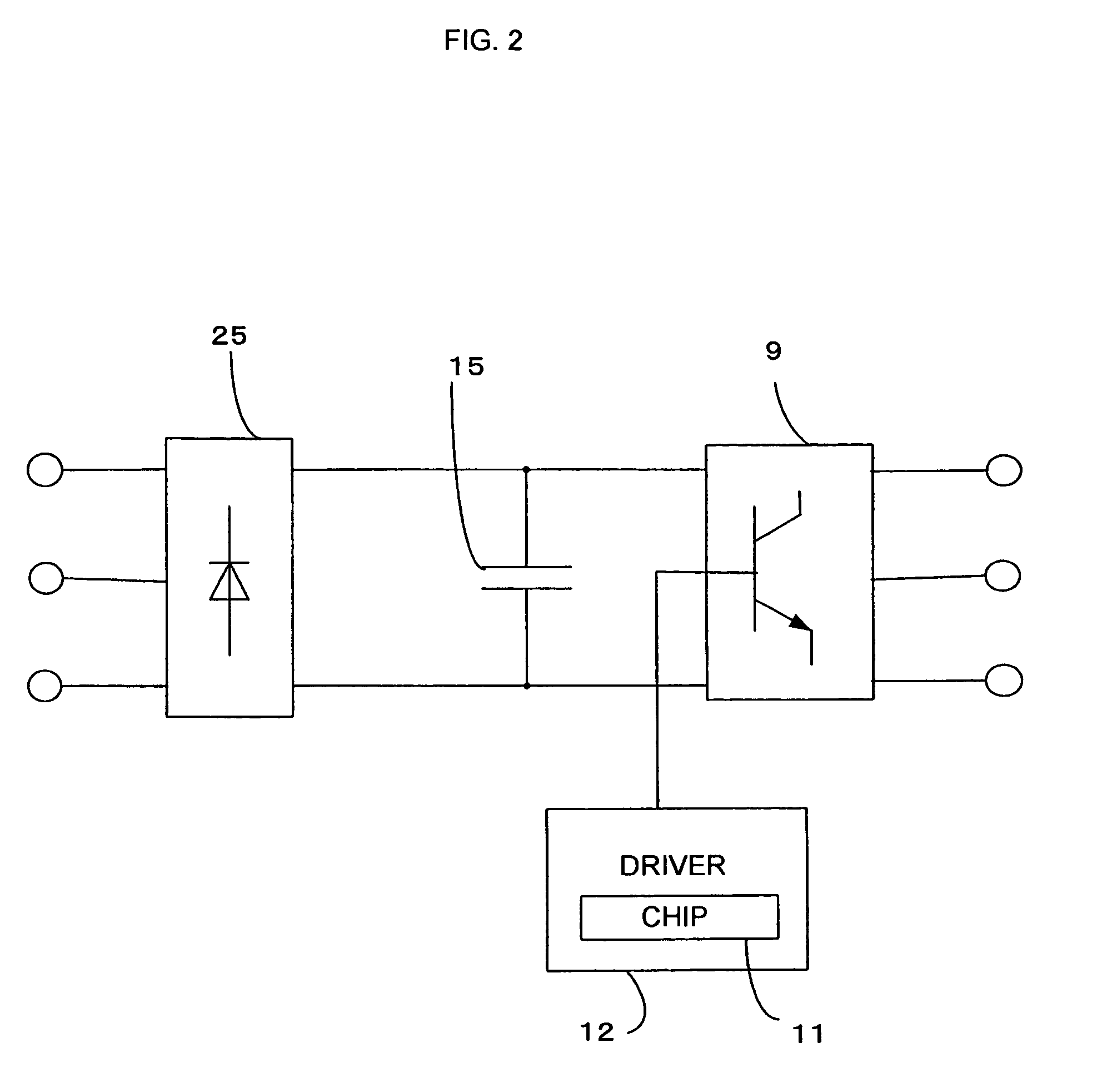
[0028]An embodiment according to the present invention is explained using FIG. 1-FIG. 3. FIG. 1 is an exploded perspective view illustrating a controller using a modular heat-radiation structure according to the embodiment of the present invention; FIG. 2 is an internal circuit diagram illustrating the controller represented in FIG. 1; and FIG. 3 is an exploded perspective view illustrating the modular heat-radiation structure represented in FIG. 1. In FIG. 1, a controller 1 using the modular heat-radiation structure includes a printed circuit board 3, chips 11 and electrolytic capacitors 15 mounted on the printed circuit board 3, a power module 5, fixed to the printed circuit board 3 through a heat shield 9, in which a transistor generating heat is encapsulated, a heat-radiation fin 7 for radiating heat of the power module 5, and a case 20, composed of a bottom board 24 and a cover 22 formed stepwise to have two steps, for storing the heat shield 9.

[0029]Moreover, regarding the con...

embodiment 2

[0034]Another embodiment according to the present invention is explained using FIG. 1, FIG. 4, and FIG. 5. FIG. 4 is a transverse sectional view (a) of the controller represented in FIG. 1, and a perspective view (b) of a unit composed of a heat shield, a printed circuit board, and electrolytic capacitors; and FIG. 5 is an exploded perspective view, viewed from the bottom face, of the controller represented in FIG. 4. The same symbols in FIG. 4 and FIG. 5 as those in FIG. 1-FIG. 3 are assigned to the same or equivalent elements, and the explanation is omitted.

[0035]In FIG. 1, FIG. 4, and FIG. 5, the controller is characterized to be separated into a non heat-generation portion in which the electrolytic capacitors 15, etc. whose heat generation is relatively insignificant are installed inside the case 20, and a heat-generation portion in which the heat generation such as the power module 5 is larger than that of the electrolytic capacitors 15. Moreover, the heat-generation portion an...

embodiment 3

[0043]Another embodiment according to the present invention is explained using FIG. 8 and FIG. 9. FIG. 8 is a perspective view illustrating a controller according to the other embodiment; meanwhile, FIG. 9 is a perspective view (a) illustrating a unit composed of a diode stack, a module, a heat shield, and a printed circuit board, and a perspective view (b) illustrating the heat shield. The same symbols in FIG. 8 and FIG. 9 as those in FIG. 4-FIG. 5 are assigned to the same or equivalent elements, and the explanation is omitted.

[0044]In FIG. 8 and FIG. 9, the controller is provided with the printed circuit board 3, the heat-generating diode stack 25 having a rectangularly-and-vertically-arranged second main unit 25h whose lead lines 25L as the lead are fixed to the printed circuit board 3, the heat-radiation fin 7 having a mouth 7h for protruding the second main unit 25h of the diode stack 25 and also having the folds 7b, and a clip 301, having elasticity towards the open / close move...


PUM


Abstract

A modular heat-radiation structure includes a module for generating heat, including a first main unit having a heat-radiation fin, fixed to the top face of the first main unit for radiating heat generated in the module and a resin-made and insulating heat shield inserted between the printed circuit board and the first main unit.

Description

BACKGROUND ART[0001]A conventional modular heat-radiation structure is explained referring to Japanese Laid-Open Patent Publication 111,250 / 2002. According to this Patent Publication, a controller includes a printed circuit board, a module mounted on the printed circuit board, a screw for fixing the module with a heat-radiation fin for radiating heat that the module generates, and a plate-like fixture provided with a hook. The fixture is inserted between the printed circuit board and the module, and is fixed to the printed circuit board by the hook; moreover, the fixture fixes the printed circuit board with the module.[0002]According to such modular heat-radiation structure, when the module is mounted so as to float over the printed circuit board due to a reason such as improvement of its mounting efficiency, by mounting onto the printed circuit board the plate-like fixation disc sandwiched between the module and the printed circuit board, an integral unit of the heat-radiation plat...

Claims


Application Information

Patent Timeline
Patent Type & Authority Patents(United States)
IPC IPC(8): H05K7/20H01L23/34F28F7/00H01L23/40H05K1/02H05K1/14H05K1/18H05K3/30
CPCH01L23/34H01L23/4006H01L23/4093H05K3/301H01L2924/0002H01L2023/405H01L2023/4062H01L2023/4087H05K1/0203H05K1/141H05K3/306H05K2201/062H05K2201/10515H05K2201/10689H05K2201/2036H01L2924/00
Inventor YAMADA, HIROSHIABE, TOMONORITAKIKOSHI, KEIICHI
Owner MITSUBISHI ELECTRIC CORP
Why Eureka
Try Eureka