Hybrid aerial and terrestrial vehicle

a terrestrial and hybrid technology, applied in the field of unmanned vehicles, can solve problems such as easy system flies, and achieve the effects of low manufacturing cost, simple design, and high safety

Active Publication Date: 2015-06-23
ILLINOIS INSTITUTE OF TECHNOLOGY
View PDF22 Cites 59 Cited by
  • Summary
  • Abstract
  • Description
  • Claims
  • Application Information

AI Technical Summary

Benefits of technology

[0008]Flight is desirably achieved using a rotorcraft flying device, which can have different configurations based on the number of rotors used. Single rotor, coaxial rotors, tandem rotors, tricopter, quadcopter, hexacopter, and octocopter are all different types of rotorcrafts that can serve as the flying agent of the hybrid system. Connecting this rotorcraft with a rolling cage through one or more revolute joints makes terrestrial locomotion possible. As used herein, “terrestrial” includes both solid surfaces and liquid surfaces, such as bodies of water. This design allows the cage to roll freely with respect to the flying system. The rolling cage is desirably not powered directly, and freely rolls due to the rotor thrust of the flying device alone.
[0009]During flight, the rotor actuator(s) provide enough lift to overcome the weight of the vehicle, and the system functions as a regular flying system; it can move by rolling or pitching and change direction by changing its yaw angle. For terrestrial locomotion, the rotorcraft must first pitch about the revolute joint center (see FIG. 12). In this configuration, the thrust of the rotor(s) results in cage rolling on the ground, and the vehicle moves forward. Changing the direction is also possible by changing the vehicle's yaw angle. In terrestrial mode the system only needs to overcome the ground friction which is much lower compared to the vehicle's weight. Therefore, rolling on the ground is much more efficient than flying, and the vehicle's operation time and range is increased compared to the aerial-only system.
[0010]Combining the terrestrial and aerial locomotion modes in a hybrid design incorporates the advantages of both modes in a single system. Adding a reliable terrestrial locomotion structure to an aerial vehicle provides improved efficiency, which extends operation time and range. On the other hand, adding flight capabilities to a terrestrial system eliminates the problem of obstacle negotiation. When an obstacle is encountered, the system easily flies over it.
[0012]Using the same actuators for both forms of locomotion greatly simplifies the system's mechanical and control complexity. Combining the terrestrial and aerial locomotion modes in a hybrid design incorporates the advantages of both modes in a single vehicle. Adding a reliable terrestrial locomotion mode to a MAV provides improved efficiency, which extends operation time and range. On the other hand, adding flight capabilities to a terrestrial vehicle eliminates the problem of obstacle negotiation. When an obstacle is encountered, the system easily flies over it.
[0014]The invention has a simple design. This makes it easy and low cost to manufacture. The flying system does not have a new or specific design requirement. Any regular flying rotorcraft system, for which there are many well developed samples available, can be employed as the flying agent. The rolling cage is desirably impact resistance and durable against the shocks that aggressive landings or crashes of the flying device can cause. In one embodiment, polycarbonate and carbon fiber materials were used to fabricate the prototype system. As detailed below, the fabricated cage was / is able to successfully resist shocks and forces.
[0015]To reduce dissipation of energy during terrestrial locomotion, the joint connecting the rolling cage and the flying system should have the minimum possible friction. Mounting bearings at the position of the joints helps reduce the friction.

Problems solved by technology

When an obstacle is encountered, the system easily flies over it.

Method used


Image

  • Hybrid aerial and terrestrial vehicle
  • Hybrid aerial and terrestrial vehicle
  • Hybrid aerial and terrestrial vehicle

Examples


Embodiment Construction

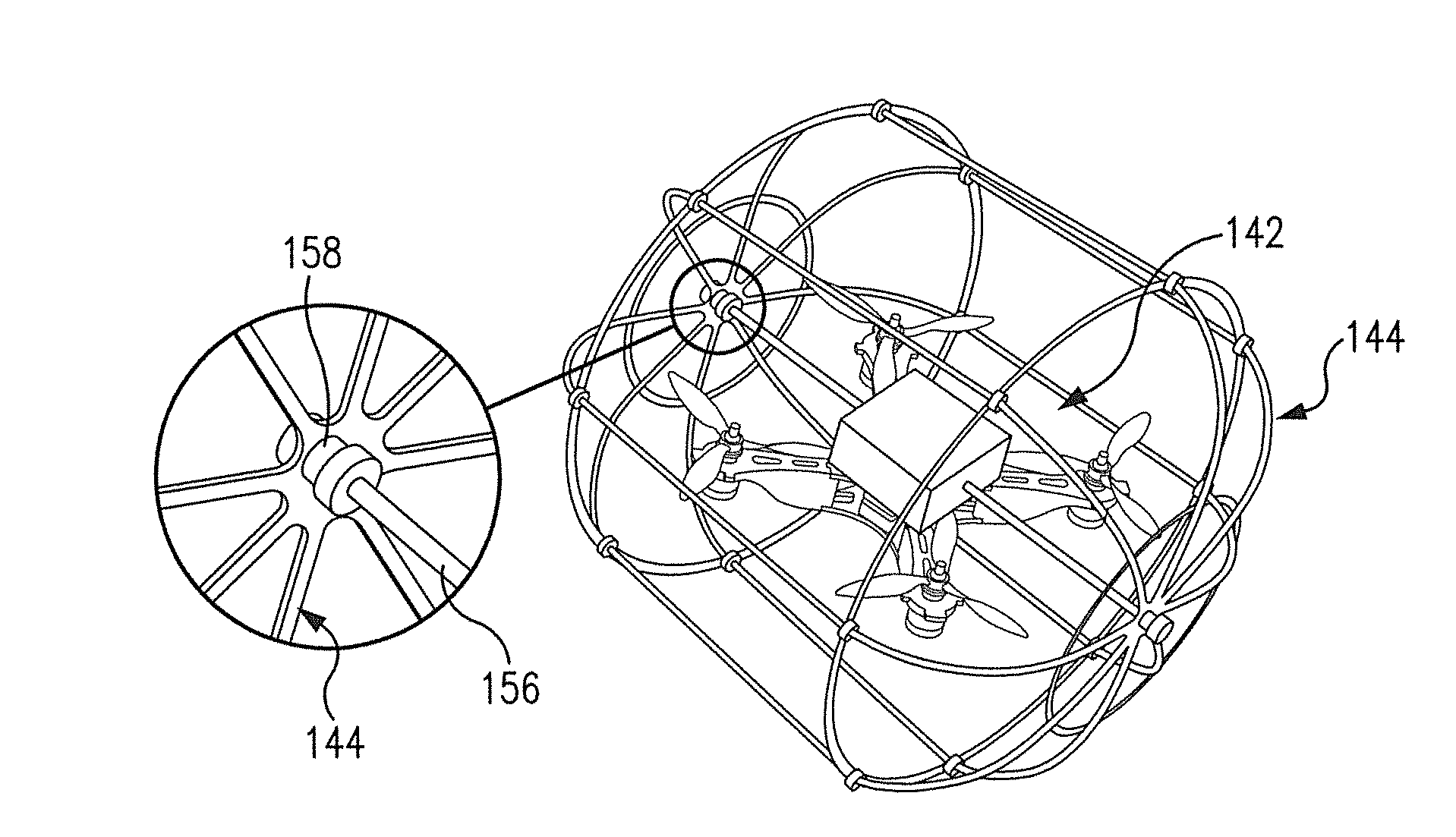
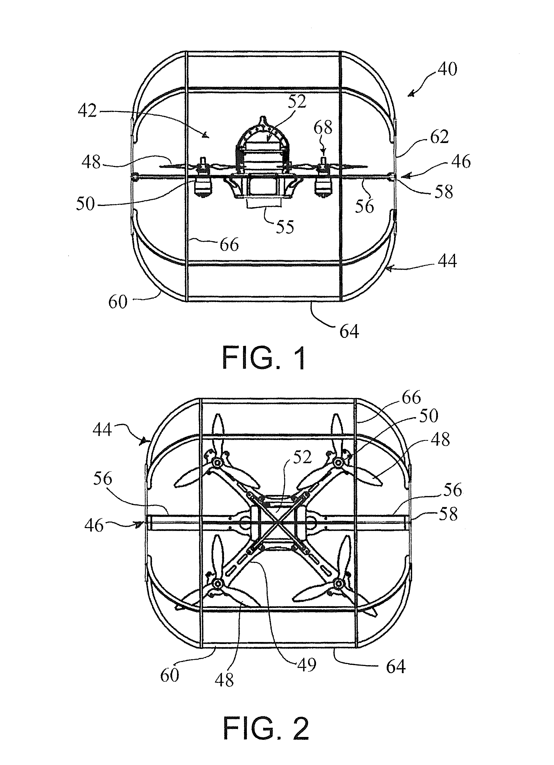
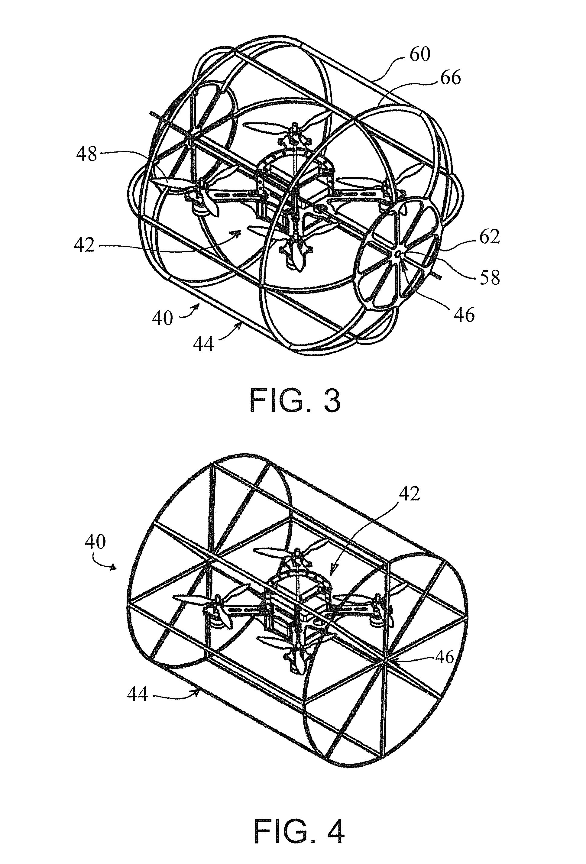
[0032]This invention provides a mobile autonomous or remote-controlled vehicle, such as a MAV, capable of both aerial and terrestrial locomotion. Flight is desirably achieved through a suitable rotor configuration, such as a quadrotor with four actuators that provide the required thrust. Adding a non-powered rolling cage to the vehicle makes terrestrial locomotion possible using the same actuator set and control system. Thus, neither the mass nor the system complexity is increased by inclusion of separate actuators for terrestrial and aerial locomotion. An analysis of the system's energy consumption demonstrated that during terrestrial locomotion, the vehicle only needs to overcome rolling resistance and consumes much less energy compared to the aerial mode. This solves one of the most vexing problems of quadrotors and rotorcraft in general, namely their short operation time. Experimental results showed that the hybrid vehicle can travel a distance four times greater and operate alm...


PUM


Abstract

A vehicle capable of both aerial and terrestrial locomotion. The terrestrial and aerial vehicle includes a flying device and a rolling cage connected to the flying device by at least one revolute joint. The rolling cage at least partially surrounds the flying device and is free-rolling and not separately powered.

Description

CROSS REFERENCE TO RELATED APPLICATION[0001]This application claims the benefit of U.S. Provisional Application, Ser. No. 61 / 726,335, filed on 14 Nov. 2012. The provisional application is hereby incorporated by reference herein in its entirety and is made a part hereof, including but not limited to those portions which specifically appear hereinafter.[0002]This invention was made with government support under award N00014-10-1-0769 awarded by Office of Naval Research. The government has certain rights in the invention.BACKGROUND OF THE INVENTION[0003]1. Field of the Invention[0004]This invention is directed to an unmanned vehicle, and more particularly to an autonomous or remotely controlled vehicle capable of both aerial and terrestrial locomotion.[0005]2. Discussion of Related Art[0006]The ability to quickly reach a goal location without needing to navigate obstacles or challenging terrain makes aerial vehicles an excellent choice in applications like search and rescue or military...

Claims


Application Information

Patent Timeline
Patent Type & Authority Patents(United States)
IPC IPC(8): B60F5/02A63H27/133B64C25/36B64C39/02A63H27/00A63H33/00
CPCB60F5/02B64C25/36B64C39/028A63H33/005A63H27/12B64C39/024B64C2201/127B64C2201/027B64C2201/042B64U10/13B64U50/19B64U2101/30B64C37/00
Inventor KALANTARI, ARASHSPENKO, MATTHEW
Owner ILLINOIS INSTITUTE OF TECHNOLOGY
Why Eureka
Try Eureka