Air inlet for aircraft propulsion unit having a structure resistant to excess pressure and a process for repairing an air inlet of an aircraft propulsion unit

a technology of aircraft propulsion unit and air inlet, which is applied in the direction of machines/engines, combustion air/fuel air treatment, transportation and packaging, etc., can solve the problems of unsatisfactory solution and high load that may damage the region, and achieve the effect of simple, economic and efficien

Active Publication Date: 2015-06-23
AIRBUS OPERATIONS (SAS)
View PDF17 Cites 6 Cited by
  • Summary
  • Abstract
  • Description
  • Claims
  • Application Information

AI Technical Summary

Benefits of technology

[0013]It is a particular objective of the invention to provide a simple, economic and efficient solution to this problem, allowing the above-mentioned disadvantages to be avoided.
[0014]One particular subject of the invention is an air inlet for the nacelle of an aircraft propulsion unit, which has good sound-insulating and / or draining capability and is not subject to risks of damage due to phenomena of overpressure of the type described above.
[0049]The process of the invention therefore allows the repair of the inner envelope of an air inlet when this inner envelope has been damaged, in particular due to overpressure phenomena of the type described above, whilst protecting the repaired part of the inner envelope against the consequences of any future exposure to these overpressure phenomena.
[0051]The above-mentioned second fold also allows the ensured continuity of the radially inner surface of the inner envelope at the junction between the impermeable panel and the remainder of the inner envelope.

Problems solved by technology

Yet, the permeability of the inner envelope being inherently limited, this overpressure generally translates as a load applied to the region under consideration of the inner envelope during a short period in which equilibrium is set up between the pressures either side of this inner envelope, in particular at the time of a change in engine speed of the turbojet engine.
This load may be of sufficiently high intensity to damage the region under consideration of the inner envelope.
However, this solution is not entirely satisfactory owing to the limited permeability of the inner envelope which remains subject to forces liable to damage this inner envelope.

Method used


Image

  • Air inlet for aircraft propulsion unit having a structure resistant to excess pressure and a process for repairing an air inlet of an aircraft propulsion unit
  • Air inlet for aircraft propulsion unit having a structure resistant to excess pressure and a process for repairing an air inlet of an aircraft propulsion unit
  • Air inlet for aircraft propulsion unit having a structure resistant to excess pressure and a process for repairing an air inlet of an aircraft propulsion unit

Examples


first embodiment

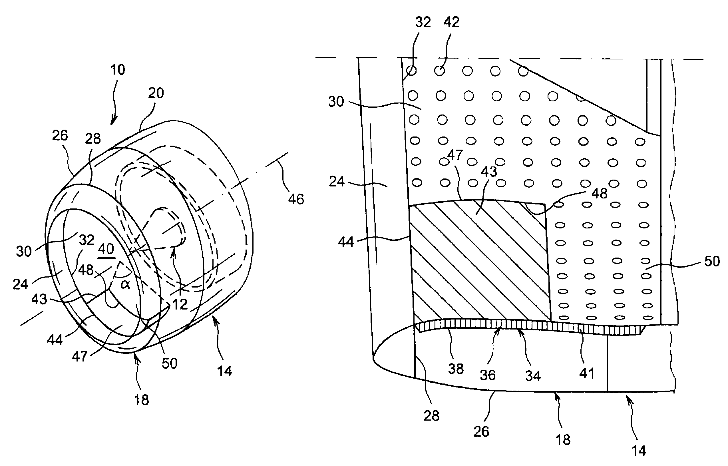
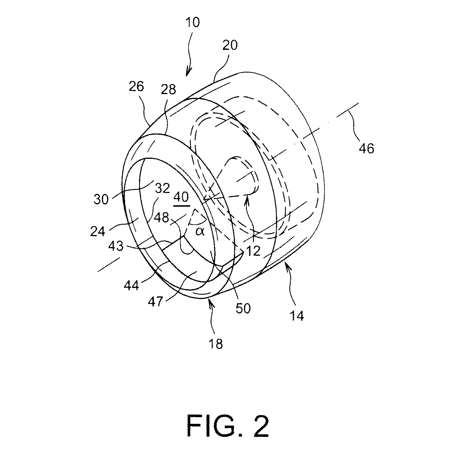
[0074]In a first embodiment, illustrated in FIGS. 1 to 3, the portion 43 devoid of air passage orifices is formed of an impermeable panel 47, formed for example by the lay-up of three folds of carbon fibres, this impermeable panel 47 being set in a recess 48 of mating shape arranged in the upstream edge of at least one openwork panel 50 of the inner envelope 30.

[0075]When the inner envelope 30 is formed of several curved panels that are circumferentially adjacent, the above-mentioned recess 48 may be formed in the upstream edge of a single panel, or else it may be formed jointly in the upstream edge of several of these panels.

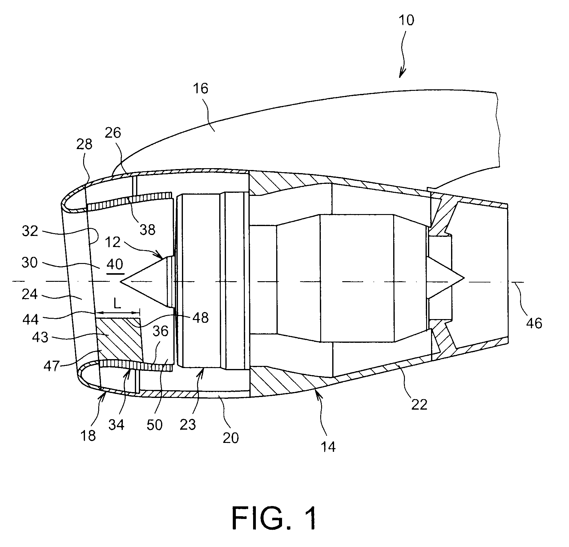
[0076]As can be seen in FIGS. 1 and 3, it is to be noted that the honeycomb structure 36 extends underneath the portion 43 of the inner envelope 30 which is devoid of air passage orifices. This is not essential for the invention but may contribute towards the rigidity of the inner structure 34 of the air inlet 18 and it may also facilitate the manufacture of th...

second embodiment

[0079]In the invention illustrated FIG. 4, the portion 43 of the inner envelope 30 that is devoid of air passage orifices is made in a single piece with the lip 24 of the air inlet 18 and extends projecting backwardly from the radially inner downstream edge 32 of the lip 24 so that it fits into the above-described recess 48.

[0080]In the example illustrated FIG. 4, the above-mentioned portion 43 is bell-shaped whose top part 52 is oriented downstream, which means that the shape of the recess 48 in FIG. 4 differs from the shape of the recess 48 in FIGS. 1 to 3.

[0081]In this second embodiment, the continuity between the lip 24 and the portion 43 devoid of air passage orifices may permit a further increase in the resistance of the inner envelope 30 against the above-described overpressure phenomena.


PUM

PropertyMeasurementUnit
angleaaaaaaaaaa
distanceaaaaaaaaaa
impermeableaaaaaaaaaa

Abstract

An air inlet for nacelle of an aircraft propulsion unit comprising an inner envelope provided with a plurality of orifices for passage of fluid passing through the envelope, and a lip connected to the upstream edge of the inner envelope, and having a portion devoid of orifices for passage of fluid with an axial span of between 20% and 90% of the span of the inner envelope, and a circumferential span a of between 60° and 150° about a longitudinal axis of the air inlet. A process for repairing an air inlet comprising cutting out a recess in an upstream edge of an inner envelope of the air inlet, then arranging and fixing an impermeable panel in the recess so as to create an air inlet of the type described above.

Description

TECHNICAL FIELD[0001]The present invention pertains to the field of aircraft propulsion units, and more particularly concerns the air inlets of nacelles of aircraft turbojet engines.STATE OF THE PRIOR ART[0002]An aircraft is propelled by one or more propulsion units which are each attached to the aircraft via a pylon generally located underneath a wing or at the fuselage and which each comprise a turbojet engine housed in a nacelle.[0003]A nacelle generally assumes the form of a structure comprising an air inlet upstream of the turbojet engine, a median section intended to surround a fan of the turbojet engine, and a downstream section integrating thrust reversing means and intended to surround a combustion chamber and one or more turbines of the turbojet engine.[0004]The air inlet comprises firstly an annular lip forming the leading edge of the nacelle and intended to capture the air needed for feeding the fan, and one or more internal compressors of the turbojet engine, and second...

Claims


Application Information

Patent Timeline
Patent Type & Authority Patents(United States)
IPC IPC(8): B64D33/02F02C7/04F02C7/045
CPCB64D33/02F02C7/04Y10T29/49229B64D2033/0206F02C7/045B64D2033/0286Y10T137/0536
Inventor BOULET, NICOLASAFFORTIT, SEBASTIEN
Owner AIRBUS OPERATIONS (SAS)
Why Eureka
Try Eureka