Supercharge Your Innovation With Domain-Expert AI Agents!

Packaging method, packaging device and injection moulding system

a packaging method and injection moulding technology, applied in the field of packaging methods, can solve the problems of not being able to allocate the packaged plastic injection moulded parts to specific cavities, not being able to determine the cavity or cavities, and not being able in practice to achieve the effect of achieving the effect of reducing the number of cavities

Active Publication Date: 2015-06-23
WALDORF TECHN
View PDF16 Cites 4 Cited by
  • Summary
  • Abstract
  • Description
  • Claims
  • Application Information

AI Technical Summary

Benefits of technology

This invention is about a way to optimally pack plastic tip or medical reaction vessels. It suggests using a method to track the origin of the plastic parts in a packaging unit and to freely select the number of parts in a pack. The packaging unit should not be the same number as the number of cavities in the injection molding tool. The plastic parts should be organized in a common deposition plane, making it easy to set up the packaging device. The number of plastic parts in each subgroup should vary from one extraction cycle to the next. A control unit can detect the positions of the plastic parts and they can be placed next to each other without changing their relative positions. This method allows for efficient use of space when depositing in the intermediate storage.

Problems solved by technology

The drawback in the known method is that it is not possible to allocate the packaged plastic injection moulded parts to specific cavities.
This means that it is no longer possible to determine the cavity or cavities from which the plastic injection moulded parts in a given packaging unit originate.
The drawback in this arrangement is that the number A of plastic injection moulded parts to be conveyed to a packaging unit must be equal to the number K of cavities, or the number A of plastic injection moulded parts to be transferred in a packaging unit must be equal to an integral multiple of the number K of cavities.
Thus for example, with the known packaging method it is not possible in practice to load packaging units with A=105 plastic injection moulded parts from a fixed number K=32 for the cavities.
However, this is usually impracticable due to the enormous space required for loading 32 packaging units at the same time.

Method used


Image

  • Packaging method, packaging device and injection moulding system
  • Packaging method, packaging device and injection moulding system
  • Packaging method, packaging device and injection moulding system

Examples


Embodiment Construction

[0039]In the figures, identical elements and elements having the same function are the same elements are identified with the same reference figures.

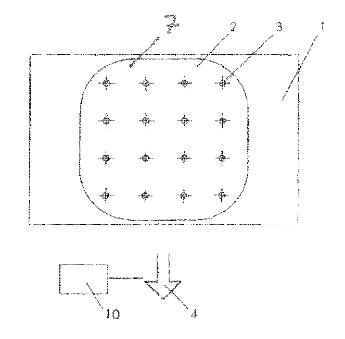
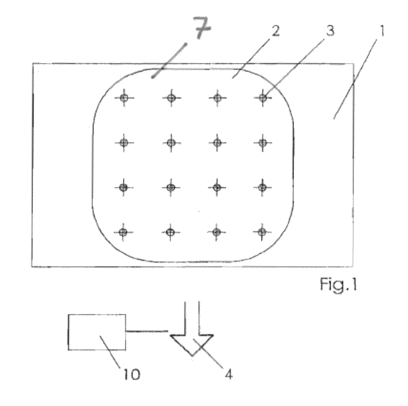
[0040]FIG. 1 shows an injection moulding device 1, including an injection moulding tool 2 with K=16 cavities 3 for the simultaneous production of 16 plastic injection moulded parts in the form of pipette tips or medical reaction vessels, as part of an injection moulding system. Injection moulding device 1 is equipped for example with extraction means 4 in the form of a vacuum gripper, preferably having a number of suction elements corresponding to the number of cavities, and which are represented only schematically by an arrow, wherein the extraction means are part of a packaging device that is not associated with a reference number. Extraction means 4 serve to extract the plastic injection moulded parts from cavities 3 and transfer the plastic injection moulded parts to an intermediate storage 5 shown in FIG. 2a. Intermediate storage 5 ...


PUM

PropertyMeasurementUnit
areaaaaaaaaaaa
sizeaaaaaaaaaa
timeaaaaaaaaaa

Abstract

The invention relates to a packaging method for packing plastic injection moulded parts (9), including:simultaneously removing K parts (9) from K cavities (3), anddepositing the parts (9) in an intermediate storage (5) andloading V packaging units (8), each having A parts (9), from the intermediate storage (5).A plurality of depositing positions (6) arranged next to each other in a deposition plane (7) is used as intermediate storage (5), and the K parts (9) are deposited equally divided among U subgroups (11) in the intermediate storage (5), and K parts (9) are removed from the K cavities (3) and are divided evenly among the U subgroups (11) until each subgroup (11) has L parts (9), wherein the quantity L of the parts (9) of a subgroup (11) corresponds to the quantity A of parts (9) to be loaded into a packaging unit (8), or an integral divisor of A. The invention further relates to a packaging device and to an injection moulding machine having such a packaging device.

Description

FIELD OF THE INVENTION[0001]The invention relates to a packaging method for packaging plastic injection moulded parts produced in the form of pipette tips or medical reaction vessels, including the following steps:[0002]extracting K plastic injection moulded parts from K cavities simultaneously, and[0003]depositing the plastic injection moulded parts in an intermediate storage, and[0004]loading each of V packaging unit(s) with A injection moulded parts from the intermediate storage, wherein V may be any integer (for example 1, 2, 3, 4 and so on).[0005]The invention further relates to a packaging device for packaging plastic injection moulded parts produced in the form of pipette tips or medical reaction vessels, including:[0006]extraction means designed for extracting K plastic injection moulded parts from K cavities simultaneously and depositing the plastic injection moulded parts in an intermediate storage, and[0007]an intermediate storage, and[0008]loading means designed for load...

Claims


Application Information

Patent Timeline
Patent Type & Authority Patents(United States)
IPC IPC(8): B65B35/30B65B19/34B65B5/08B65B5/06B65B5/10B01L9/00
CPCB65B35/30B65B19/34B65B5/08B65B5/068B65B5/105B01L9/54B29C45/1769
Inventor BOOS, CHRISTIAN
Owner WALDORF TECHN
Features
  • R&D
  • Intellectual Property
  • Life Sciences
  • Materials
  • Tech Scout
  • Unparalleled Data Quality
  • Higher Quality Content
  • 60% Fewer Hallucinations
Learn More