Free-wheeling hinge assembly

a technology of free-wheeling hinges and hinge components, which is applied in the direction of pin hinges, door/window fittings, constructions, etc., can solve the problems of increasing the complexity of the process, reducing the utility of the process, and reducing the cost of labor, parts and tools. the effect of minimizing the labor, parts and tools

Active Publication Date: 2015-06-23
ADVANCED DESIGN MFG LLC
View PDF10 Cites 7 Cited by
  • Summary
  • Abstract
  • Description
  • Claims
  • Application Information

AI Technical Summary

Benefits of technology

[0011]The present invention relates to adjustable free-wheeling hinge assemblies that can be employed readily over a wide array of applications to connect a variety of parallel oriented surface and support members, while still satisfying the complement of requirements presented by dimensions, load factors, codes, and design preferences. Furthermore, the free-wheeling hinge assemblies disclosed and claimed herein are fashioned in such a manner as to maximize the utility of the embodiments of hinge assemblies over a broad range of applications, while minimizing the labor, parts and tools required for implementation. Since the free-wheeling hinge assemblies are characterized by their universality and relative simplicity and ease of installation, they serve to fulfill both original and retrofit free-wheeling hinge requirements for multiple applications.

Problems solved by technology

Designing and assembling these hinge elements is ordinarily complicated since dimensions, load factors, code requirements, and aesthetics converge to present free-wheeling hinges which are labor and component intensive.
Moreover, with current technology, uses of free-wheeling hinge assemblies require broader ranges of hinge adaptability than what is provided in the art, and even when a custom design is presented, installation of the free-wheeling hinge assembly is time consuming.
Many ready to assemble free-wheeling hinge assemblies utilize location dependent uprights or support members that multiply the effort needed to design and assemble free-wheeling hinge assemblies and that intensify the complexity of the process.
Presently, most free-wheeling hinge assemblies are installed by the seller because of the complexity of assembling.
Thus, many free-wheeling hinge assemblies are handled fully or most fully assembled which presents bulky cargo that takes up considerable amount of space and is difficult to transport.
Additionally, when one part of a piece of a free-wheeling hinge assembly is damaged, often the entire product must be returned instead of the damaged part.
For example, when free-wheeling hinge assemblies for adjacent planar surfaces fail or are defective, often the entire free-wheeling hinge assembly must be replaced.

Method used


Image

  • Free-wheeling hinge assembly
  • Free-wheeling hinge assembly

Examples


Embodiment Construction

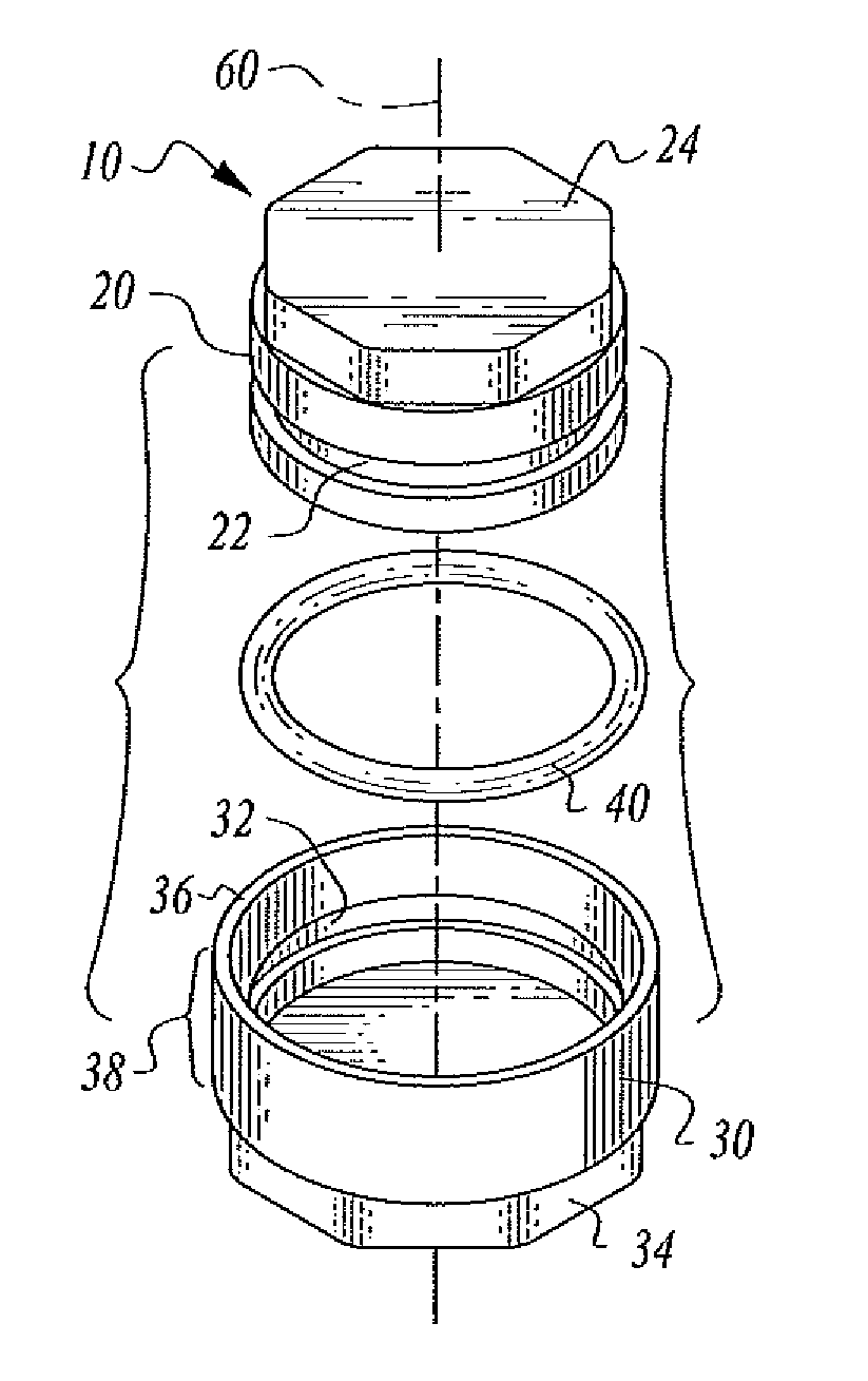
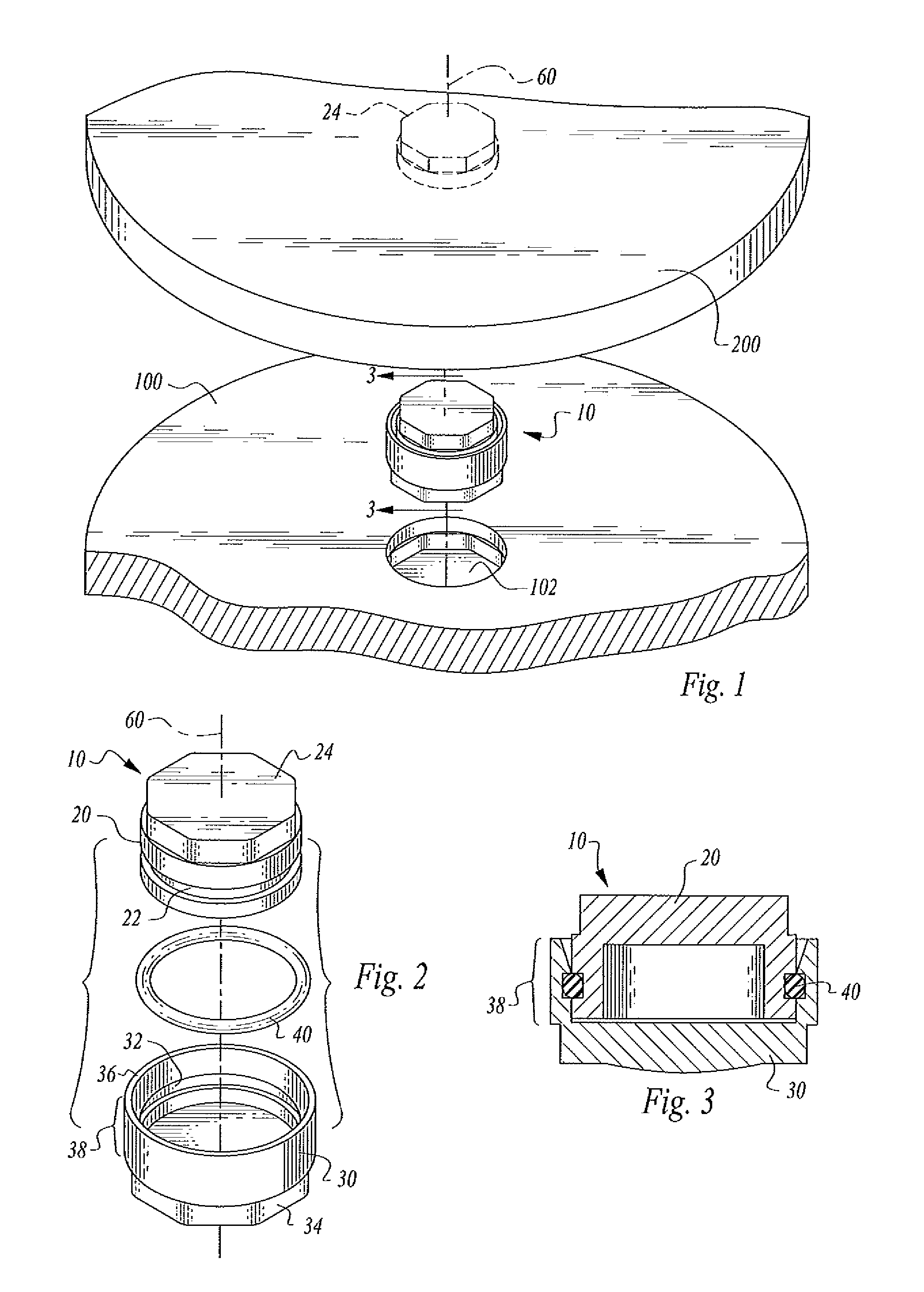
[0018]This detailed description merely describes exemplary embodiments and is not intended to limit the scope of the claims in any way. Indeed, the invention as claimed is broader than and unlimited by, the exemplary embodiments, and the terms used in the claims have their full ordinary meaning. For example, while the specific embodiments described herein relate to various assemblies using the free-wheeling hinge for use alone, or in conjunction with a plurality of lockable hinges in securing bracketing components or bracketing assemblies integrally or to other external structures, and / or immobilizing and / or adjusting one component with respect to another component about a common axis, the exemplary features and embodiments of the present application may additionally or alternatively be applied to other types of assemblies having combined locking / free-wheeling hinge arrangements, including, for example, various types of portable screens, panel bracketing, extending ladders, extendin...


PUM


Abstract

A free-wheeling hinge assembly includes a base element, a cap element, and an internal pivot assembly allowing the cap element to pivot 360 degrees transversely to a hinge assembly central axis and in relation to the base element. Geometric ends of the hinge assembly allow insertion into any two component corresponding geometric recesses to be so pivoted and repositioned.

Description

CROSS-REFERENCES TO RELATED APPLICATIONS[0001]None.STATEMENT REGARDING FEDERALLY SPONSORED RESEARCH OR DEVELOPMENT[0002]None.REFERENCE TO A MICRO-FICHE APPENDIX[0003]None.TECHNICAL FIELD[0004]This invention relates to a free-wheeling hinge assembly that, for instance, is adaptable to ready-to-assemble components for connecting one or more substantially external support member(s) defined by the particular utility of the overall assembly to at least one fixed support structure, and for providing a free-wheeling hinge assembly to positionally adjust and secure a planar member 360 degrees about a central hinge axis orthogonally disposed to the support structure.BACKGROUND OF THE INVENTION[0005]Adjustable and lockable hinge assemblies for bracketing are well known in the art and typically comprise a limited degree of range of motion aligned with a central hinge axis, as exemplified by door hinge assemblies.[0006]Designing and assembling these hinge elements is ordinarily complicated sinc...

Claims


Application Information

Patent Timeline
Patent Type & Authority Patents(United States)
IPC IPC(8): E05D5/10E05D7/00
CPCE05D7/00E05D3/02
Inventor MCGRATH, ANDREW H.
Owner ADVANCED DESIGN MFG LLC
Why Eureka
Try Eureka