Position indicator

a technology of position indicators and indicators, applied in the direction of instruments, force/torque/work measurement apparatuses, fluid pressure measurement, etc., can solve the problems of high cost, complicated configuration of position indicators, and laborious assembling of position indicators, so as to detect force surely and efficiently

Active Publication Date: 2015-06-23
WACOM CO LTD
View PDF22 Cites 27 Cited by
  • Summary
  • Abstract
  • Description
  • Claims
  • Application Information

AI Technical Summary

Benefits of technology

[0030]According to various embodiments of the invention, the position indicator includes a capacitor formed of a semiconductor element in a housing, and the pressure corresponding to the force applied to one end part of the housing is applied to the semiconductor element via a pressure transmitting member having a predetermined elasticity. Thus, the following position indicator can be provided. Specifically, the position indicator has pressure resistance against the force applied to one end part of the housing and can detect the force surely and efficiently. In addition, the position indicator has shock resistance against an unexpected shock-like pressure.

Problems solved by technology

This causes a problem that the configuration of the position indicator is complicated and assembling of the position indicator takes a lot of labor hours and high cost.

Method used


Image

  • Position indicator
  • Position indicator
  • Position indicator

Examples


first embodiment

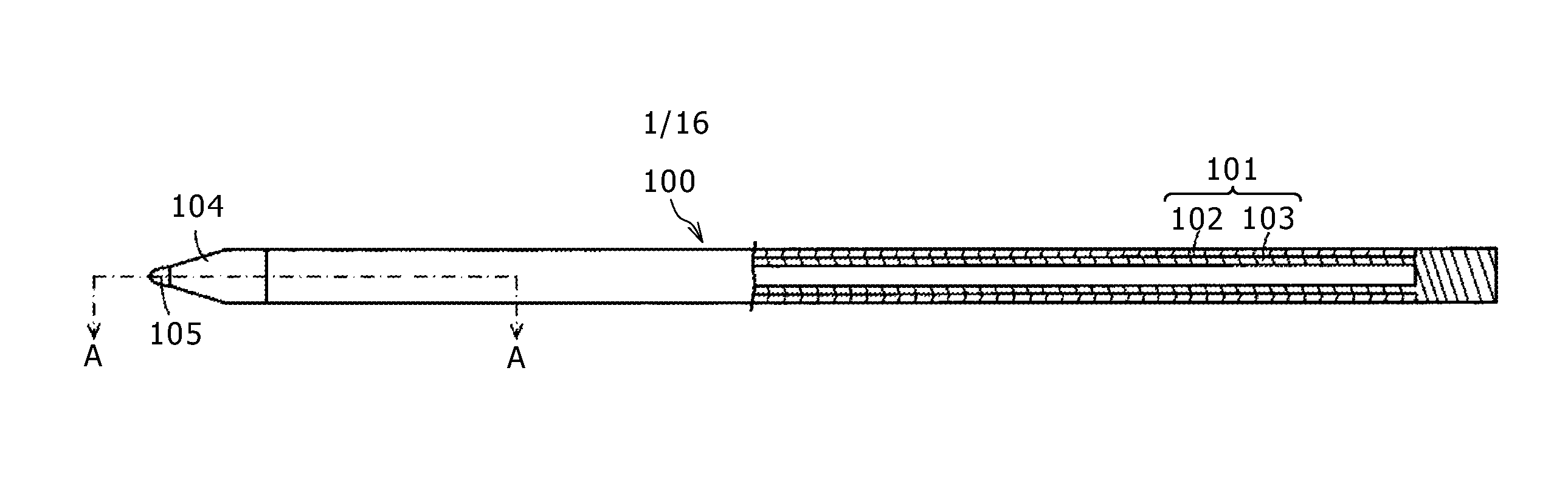
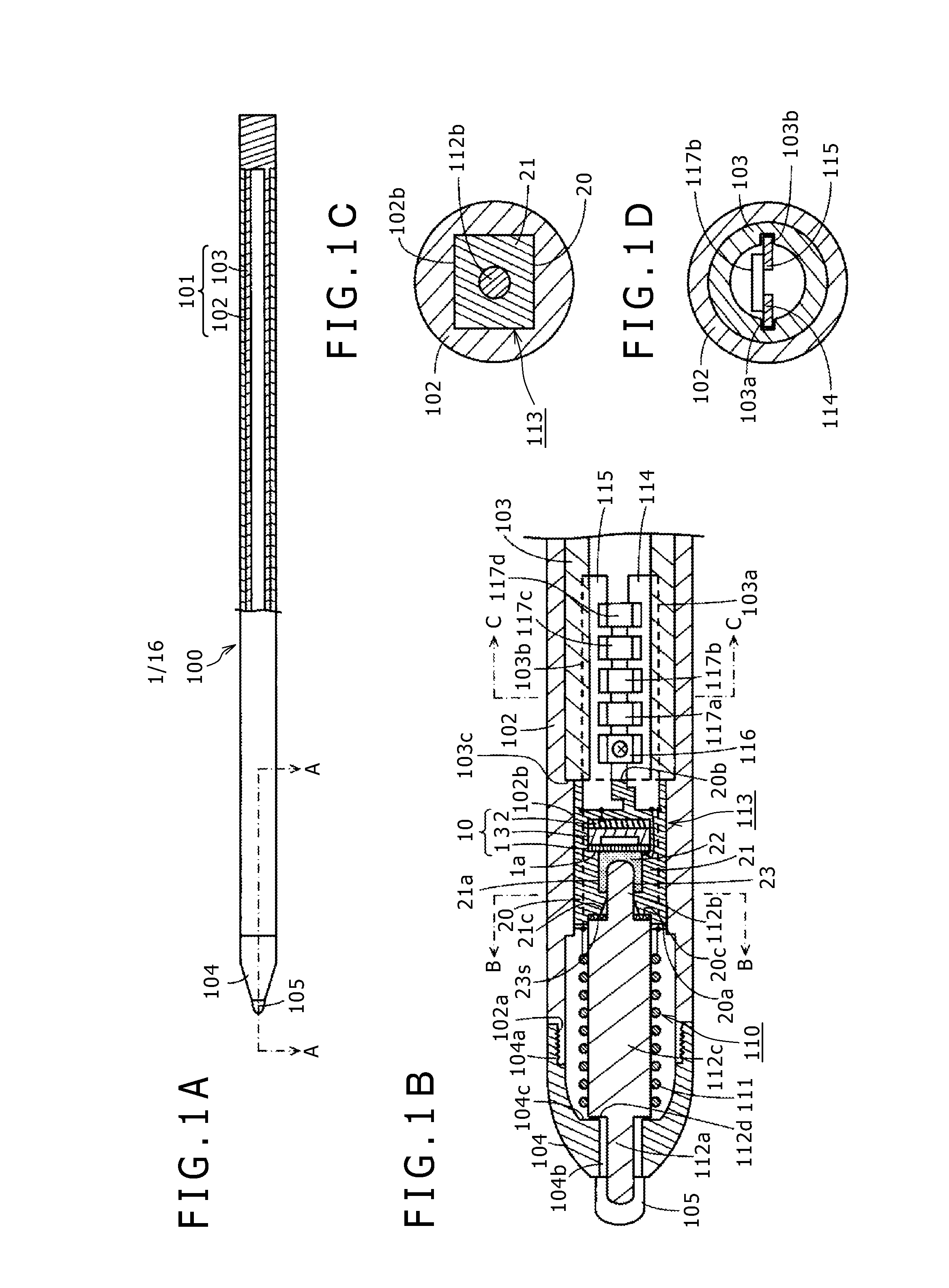
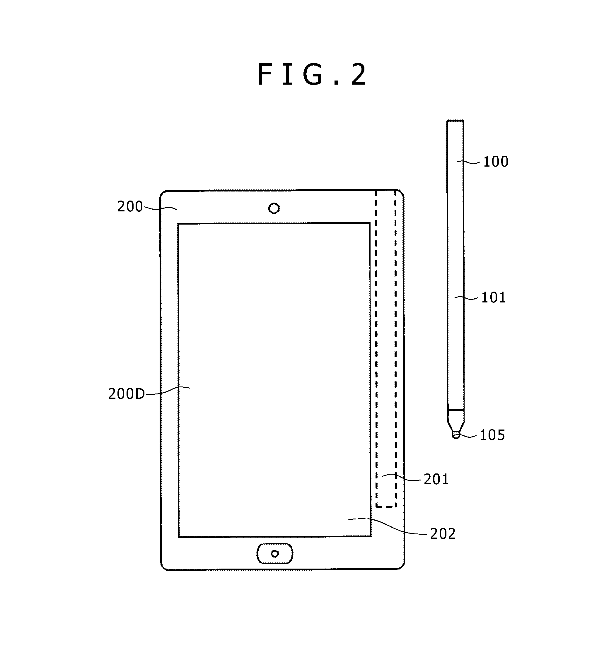
[0049]FIGS. 1A-1D are diagrams for explaining an embodiment of a position indicator according to this invention. FIG. 2 shows one example of electronic apparatus 200 using a position indicator 100 of this embodiment. In this example, the electronic apparatus 200 is a high-function cell-phone terminal having a display screen 200D of a display device such as LCD (Liquid Crystal Display) and includes a position detecting device 202 of the electromagnetic induction system under the display screen 200D.

[0050]The housing of the electronic apparatus 200 of this example has a housing recessed hole 201 to house the position indicator 100 having a pen shape. The user pulls out the position indicator 100 housed in the housing recessed hole 201 from the electronic apparatus 200 according to need and performs position indication operation on the display screen 200D.

[0051]In the electronic apparatus 200, when the position indication operation is performed on the display screen 200D by the positio...

modification examples of first embodiment

Adjustment of Writing Pressure-Capacitance Change Characteristic

first example

[0107]In the pressure detecting chip 10 of the pressure sensing semiconductor device 113 of the above-described first embodiment, when the thickness t of the single-crystal silicon forming the first electrode 1, to which pressure (writing pressure) is applied, is changed, the amount of bending of the first electrode 1 that corresponds to the writing pressure will vary. Therefore, by selecting a desired thickness t of the first electrode 1, the change characteristic of the capacitance Cv of the pressure detecting chip 10 as a function of the writing pressure can be varied.

[0108]FIG. 6 is a characteristic diagram showing an example of the change characteristic of the capacitance Cv as a function of the writing pressure applied to the pressure detecting chip 10. As shown in FIG. 6, when the thickness t of the first electrode 1 is t1, the change characteristic of the capacitance Cv of the pressure detecting chip 10 as a function of the applied writing pressure is as shown by a curve 40....


PUM

PropertyMeasurementUnit
diameteraaaaaaaaaa
diameteraaaaaaaaaa
capacitanceaaaaaaaaaa

Abstract

A position indicator includes a capacitor having a capacitance that changes in correspondence to a force applied to one end part of a housing. The capacitor is configured by a pressure detecting chip that includes a first electrode and a second electrode disposed opposite to the first electrode with a predetermined distance defined therebetween to have capacitance Cv formed between the first electrode and the second electrode. The capacitance Cv changes when the force applied to the one end part of the housing is transmitted to the first electrode to thereby change a relationship (e.g., the distance) between the two electrodes. A pressure transmitting member having predetermined elasticity is disposed on the first electrode such that the force applied to the one end part of the housing is transmitted to the first electrode of the semiconductor element via the pressure transmitting member.

Description

CROSS-REFERENCE(S) TO RELATED APPLICATION(S)[0001]The present application claims priority under 35 U.S.C. 119(a) of Japanese Application No. 2012-023530, filed Feb. 6, 2012, the entire content of which is incorporated herein by reference.BACKGROUND[0002]1. Technical Field[0003]This invention relates to a position indicator that is used together with a position detecting device and that has, e.g., a pen shape, and particularly to a position indicator having a writing pressure detection function to detect pressure applied to the tip part of the position indicator.[0004]2. Description of the Related Art[0005]As an input device for a personal computer and so forth, a position input device is known that uses a position detecting device that has an input surface, on which pointing operation and input of characters, figures, etc. are performed, and that detects the operation input position on the input surface by the electromagnetic induction system. Normally, for this kind of position inp...

Claims


Application Information

Patent Timeline
Patent Type & Authority Patents(United States)
IPC IPC(8): G01L1/00G01L1/22G01L1/14G06F3/0354
CPCG01L1/142G06F3/03545G06F3/046H01G5/14G06F3/033G01D5/2046G01L9/0073G06F3/0383
Inventor HORIE, TOSHIHIKOTAKIGUCHI, HIDETAKA
Owner WACOM CO LTD
Why Eureka
Try Eureka