
Lighted work mat

a technology for working mats and work surfaces, applied in the field of work mats, can solve problems such as interfering with the mechanic's ability to work properly

Active Publication Date: 2015-06-30
MANGUS LARRY P
View PDF7 Cites 10 Cited by
  • Summary
  • Abstract
  • Description
  • Claims
  • Application Information

AI Technical Summary

Benefits of technology

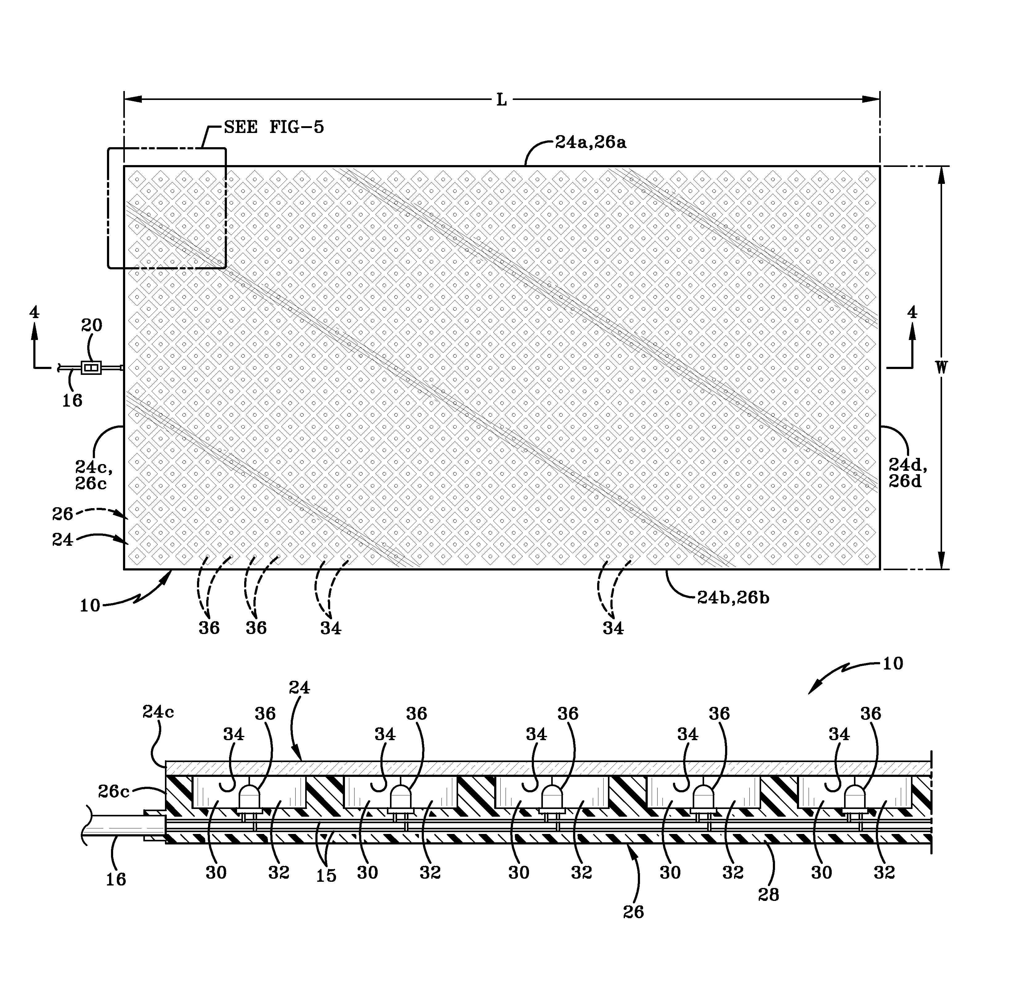
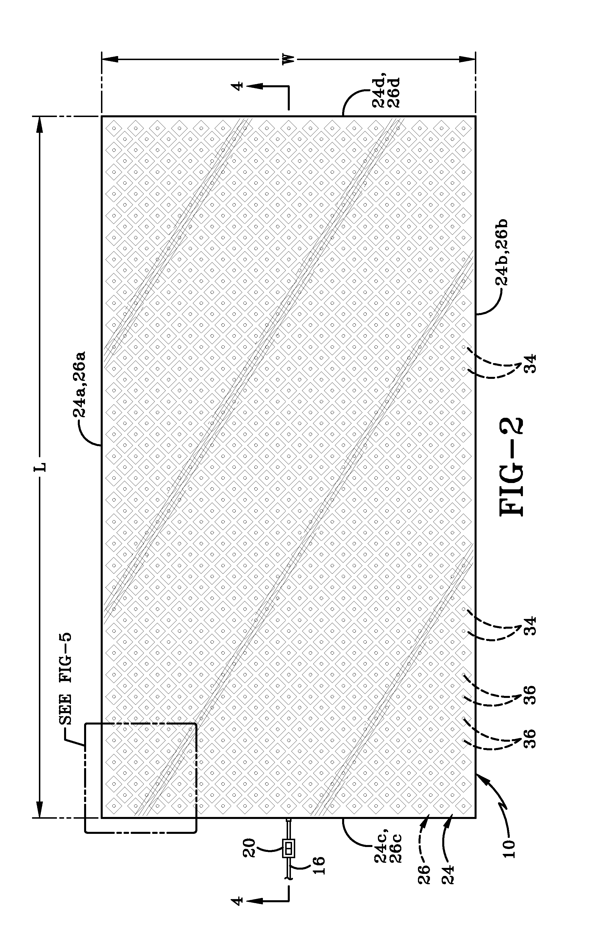
[0007]The device of the present invention comprises a modular lighted work mat made up one or more substantially flat modular panels. Each panel includes a plurality of light-emitting diodes (LEDs) embedded in a base and spaced at intervals from each other. The lighted work mat is provided with wiring to connect the LEDs and the wiring is operatively connected to a power source. A switch is provided on the work mat to activate and deactivate the LEDs. Multiple lighted work mat panels are joined together along their edges by suitable fasteners so that the mat may be made to a desired size so as to provide lighting for the entire underside of a vehicle. Panels are added or removed to adjust the size of the lighted work mat for different vehicles. A ramp may be connected to one edge of the lighted work mat to enable a mechanic's creeper to roll onto and off of an upper surface of the lighted work mat.

Problems solved by technology

If, however, the mechanic is working on the vehicle's undercarriage and does not have access to a lighted work pit, the mechanic may need to lie on the ground, slide under the vehicle and use a flashlight to see.
This, of course, causes issues because of the need to hold the flashlight.
Additionally the light source is a point light source and thus casts shadows which interfere with the mechanic's ability to work properly.

Method used


Image

  • Lighted work mat
  • Lighted work mat
  • Lighted work mat

Examples


Embodiment Construction

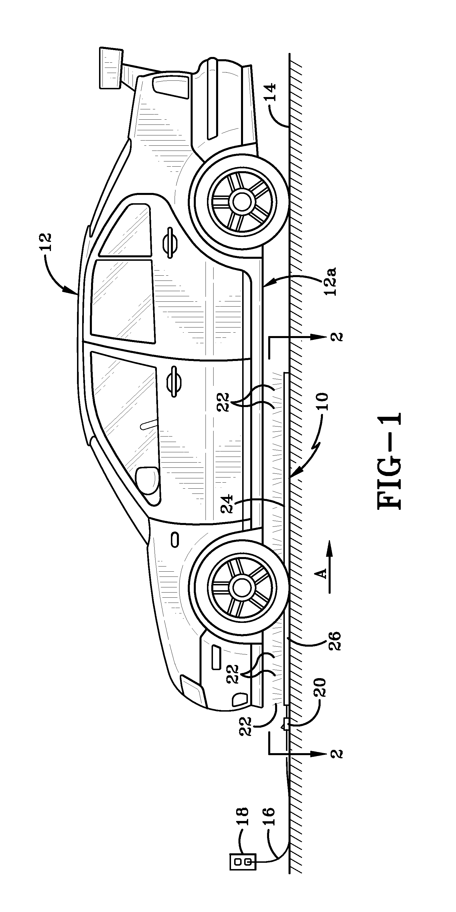
[0018]Referring to FIGS. 1-5, there is shown a lighted work mat in accordance with the present invention, generally indicated at 10. Work mat 10 is designed for use during repair or maintenance of a vehicle 12. Most particularly, work mat 10 is configured to be positioned on a surface 14 upon which vehicle 12 stands and beneath the vehicle's undercarriage 12a. Work mat 10 includes wiring 15 (FIG. 4) which is operatively connected via a power cord 16 to a remote power source, such as an AC outlet 18. (It will be understood that the power source may take other forms such as a battery, without departing from the scope of the invention.) A switch 20 is provided to activate and / or deactivate work mat 10 so that it emits light 22 (FIG. 1) or does not emit light (not shown).

[0019]Referring now to FIGS. 2-5, work mat 10 includes a base. The base includes at least a first layer 24 (FIG. 4) into which a plurality of light sources and associated wiring are embedded, as will be described hereaf...


PUM


Abstract

A modular work mat for a vehicle including a base, a plurality of light sources embedded in the base, wiring connecting the light sources; wherein the wiring is operatively connectable to a power source. The light sources preferably are LEDs. The base includes a first layer of a first material and a second layer of a second material and the LEDs are embedded between the first and second layers. The mat is connected via a power cord to a power supply and when the power supply is activated, the LEDs emit light through the first layer of the base. The work mat is placed on a surface so that the emitted light is able to illuminate a portion of the undercarriage or the entire undercarriage. The mat may be positioned beneath a portion of the vehicle's undercarriage or the vehicle may be driven onto the mat.

Description

BACKGROUND OF THE INVENTION[0001]1. Technical Field[0002]This invention relates generally to work mats. Specifically, this invention is directed to work mat having a base in which a plurality of LED's are embedded, and where the mat is positionable on a surface beneath the undercarriage of a vehicle; and the LEDs are activate to illuminate the vehicle's undercarriage from below.[0003]2. Background Information[0004]Mechanics and people skilled in personally working on their own vehicles require adequate lighting to see clearly when they are working on a vehicle. If the mechanic is working on a vehicle's engine, it is possible to position a light source in a location that enables the mechanic to see. That light source may simply be overhead lights in the garage, a flashlight of some type, or a work light that is secured somehow onto the underside of the vehicle's hood or adjacent the part of the engine the mechanic is working on.[0005]If, however, the mechanic is working on the vehicl...

Claims


Application Information

Patent Timeline
Patent Type & Authority Patents(United States)
IPC IPC(8): F21V33/00F21V15/01F21W131/10F21W131/40F21Y101/02F21Y105/00
CPCF21V15/012F21V15/01F21W2131/1005F21W2131/40F21Y2101/02F21Y2105/001F21Y2105/10F21Y2115/10B25H5/00
Inventor MANGUS, LARRY P.
Owner MANGUS LARRY P
Learn More