Large-sized combined dynamic and static multifunctional geotechnical engineering simulation testing device

A technology for geotechnical engineering and simulation test, applied in the field of large-scale combined dynamic and static multi-functional geotechnical engineering simulation test device, can solve the problems of high cost, unfavorable test line, high processing accuracy requirements, and ensure overall stiffness and strength, Improve test accuracy and good impact toughness

Active Publication Date: 2011-09-07
山东百廿慧通工程科技有限公司
View PDF9 Cites 71 Cited by
  • Summary
  • Abstract
  • Description
  • Claims
  • Application Information

AI Technical Summary

Problems solved by technology

[0017] 1. Most loading systems cannot achieve the effect of uniform and flexible loading, and a few test systems that can achieve the effect of flexible and uniform loading have not been widely used due to the complex structure or high cost of the flexible and uniform loading system
[0018] 2. The size of the model device is generally not adjustable, and the adjustable operation is relatively cumbersome. Limited by the size of the model, it is difficult to realize large-scale true three-dimensional high-in-situ stress geotechnical engineering model test research
[0019] 3. The scalability of the model test device is not strong, the function is single, and the dynamic load model test cannot be done
[0020] 4. The hydraulic loading cylinders are all installed inside the model device, between the reaction force be

Method used


Image

  • Large-sized combined dynamic and static multifunctional geotechnical engineering simulation testing device
  • Large-sized combined dynamic and static multifunctional geotechnical engineering simulation testing device
  • Large-sized combined dynamic and static multifunctional geotechnical engineering simulation testing device

Examples


specific Embodiment approach

[0061] The present invention will be further described below in conjunction with the accompanying drawings and embodiments.

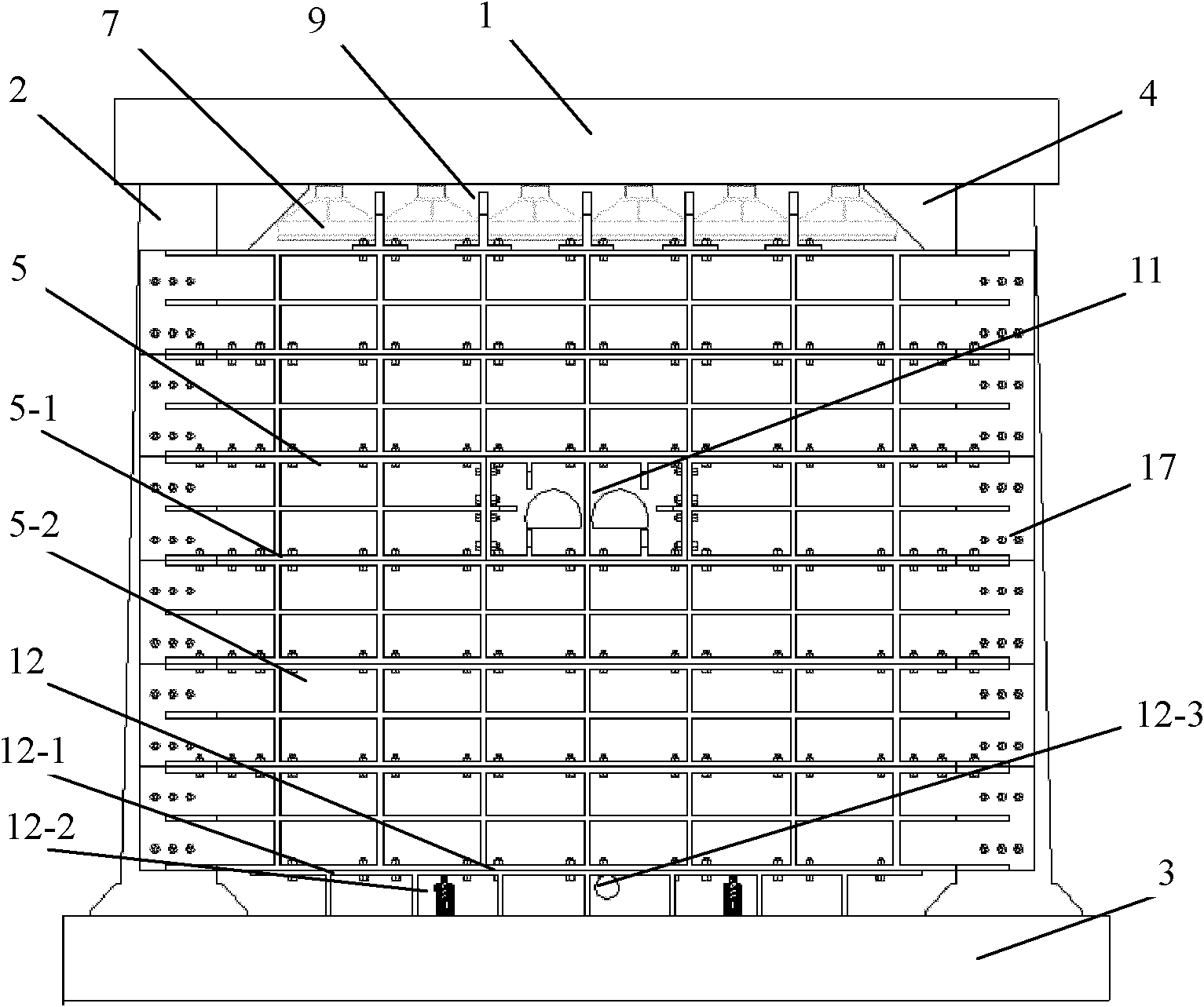
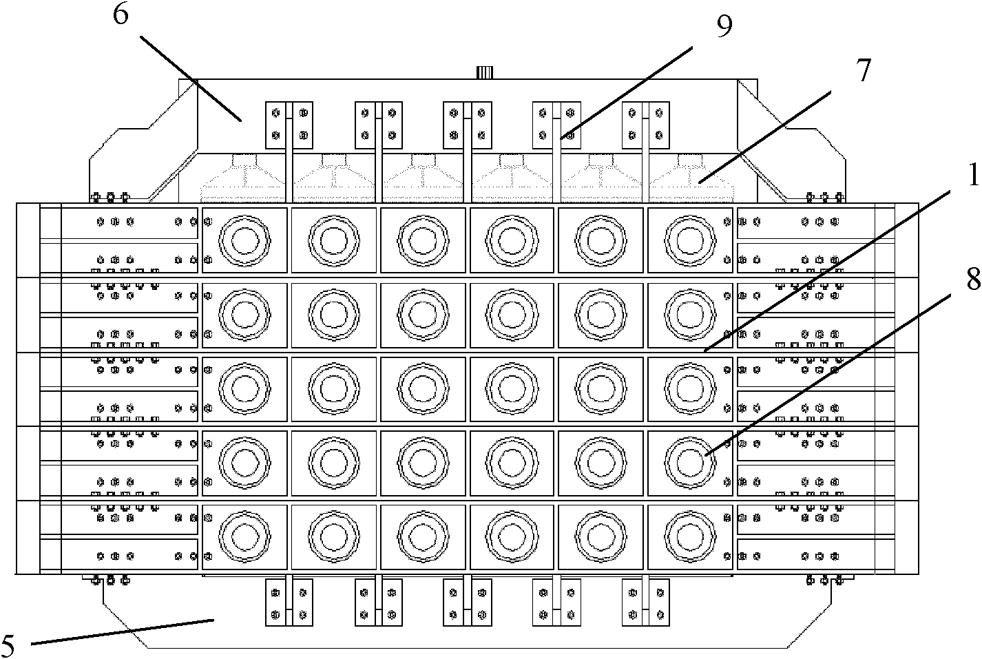
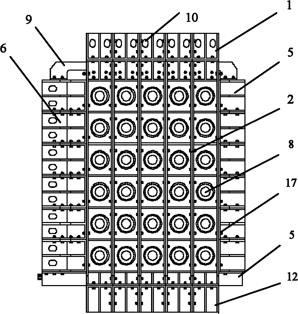
[0062] figure 1 , figure 2 , image 3 Among them, the large-scale assembled multifunctional geotechnical engineering model test device is mainly composed of an assembled reaction force bench device, a hydraulic loading system and a model transfer system. As a whole, the assembled reaction force platform device is narrow at the top and wide at the bottom, and the side is inclined. 1 and side beam 2 and between side beam 2 and bottom beam 3 are connected by flange 4 and high-strength connecting bolts 17; front visible reaction beam 5 and rear loading reaction beam 6 are connected to The side beam 2 is connected, and the bottom is connected with the model lift and translation trailer system 12; a hydraulic loading system 7 is installed in the steel grid of the top beam 1, side beam 2 and rear loading reaction beam 6; Load the system. The hydraulic lo...


PUM


Abstract

The invention relates to a large-sized combined dynamic and static multifunctional geotechnical engineering simulation testing device which comprises a plurality of counterforce stand devices, a front visible counterforce beam, a rear loading counterforce beam, an arch-shaped dynamic counterforce frame, a hydraulic loading system, a servo dynamic loading system, a model elevating translational trolley system and the like, wherein each counterforce stand device is formed by connecting a top beam, a side beam and a bottom beam through flanges and high-intensity bolts and can be combined freely according to a testing model; the left and the right parts of the front and the rear counterforce beams are connected with the side beam; the upper and the lower parts of the front and the rear counterforce beams are connected with the model elevating translational trolley system through pull rods; the hydraulic loading system is arranged in a steel grid formed by the top beam, the side beam and the rear loading counterforce beam; the arch-shaped dynamic counterforce frame is independent; and after the top beam is detached, the servo dynamic loading system can be arranged. The testing device is compact and reasonable in structure, narrow on the upper part and wide on the lower part, assembled flexibly, easy to operate, and convenient to load and observe and can be applied to planar and three-dimensional geomechanics static and dynamic model testing of geotechnical engineering under the conditions of foundation pits, side slopes and high ground stress.

Description

[0001] technical field [0002] The invention relates to a geotechnical engineering model test device, in particular to a large combined dynamic and static multifunctional geotechnical engineering simulation test device. Background technique [0003] The geomechanics model test is beneficial to highlight the main contradiction in the complex test process, and it is easy to grasp and discover the inner relationship of the phenomenon. Abroad, experts headed by Furman Green created the engineering geomechanics model test technology in the Italian Structural Model Test Institute. Subsequently, countries such as the United States, Germany, France, the United Kingdom, and Japan also carried out a large number of model test studies. In China, Tsinghua University, the Third Research Institute of the General Staff Corps of Engineering, Wuhan University, Shandong University and many other scientific research institutes have successively carried out geomechanical model test research o...

Claims


Application Information

Patent Timeline
IPC IPC(8): G01N3/00G01N3/02
Inventor 王汉鹏李术才李为腾王琦李智郑学芬徐洪峰
Owner 山东百廿慧通工程科技有限公司
Why Eureka
Try Eureka