
Concealed light detection and ranging system

a detection and range system technology, applied in distance measurement, surveying and navigation, instruments, etc., can solve the problems of difficult installation, difficult implementation of a discreet installation, and easy sight of hardware and difficult mounting of hardware,

Inactive Publication Date: 2015-06-30
LASER LIONS
View PDF8 Cites 18 Cited by
  • Summary
  • Abstract
  • Description
  • Claims
  • Application Information

AI Technical Summary

Problems solved by technology

Unfortunately, this limitation means that the hardware is easily seen and difficult to mount without damaging the vehicle in which such a device is mounted.
This further makes implementation of a discreet installation difficult.
Additionally, known systems often have bulky hardware mounted in open view.
Also, this open-view mount places sensitive electronics in harm's way for road debris, water intrusion, and the like.
Further, the optics in such systems cannot be changed or custom designed for optimal use for a specific vehicle and specific applications.
Often, this causes LIDAR jammers to be displayed in an automobile in plain sight.
This may cause the LIDAR jammer to fail to detect an enforcement device.
Further, typical LIDAR jammers may have limited options as to where in an automobile a sensor may be placed.
In view of the foregoing, it is clear that these traditional techniques are not perfect and leave room for more optimal approaches.

Method used


Image

  • Concealed light detection and ranging system
  • Concealed light detection and ranging system
  • Concealed light detection and ranging system

Examples


Embodiment Construction

[0024]Embodiments of the present invention are best understood by reference to the detailed figures and description set forth herein.

[0025]Embodiments of the invention are discussed below with reference to the Figures. However, those skilled in the art will readily appreciate that the detailed description given herein with respect to these figures is for explanatory purposes as the invention extends beyond these limited embodiments. For example, it should be appreciated that those skilled in the art will, in light of the teachings of the present invention, recognize a multiplicity of alternate and suitable approaches, depending upon the needs of the particular application, to implement the functionality of any given detail described herein, beyond the particular implementation choices in the following embodiments described and shown. That is, there are numerous modifications and variations of the invention that are too numerous to be listed but that all fit within the scope of the i...


PUM


Abstract

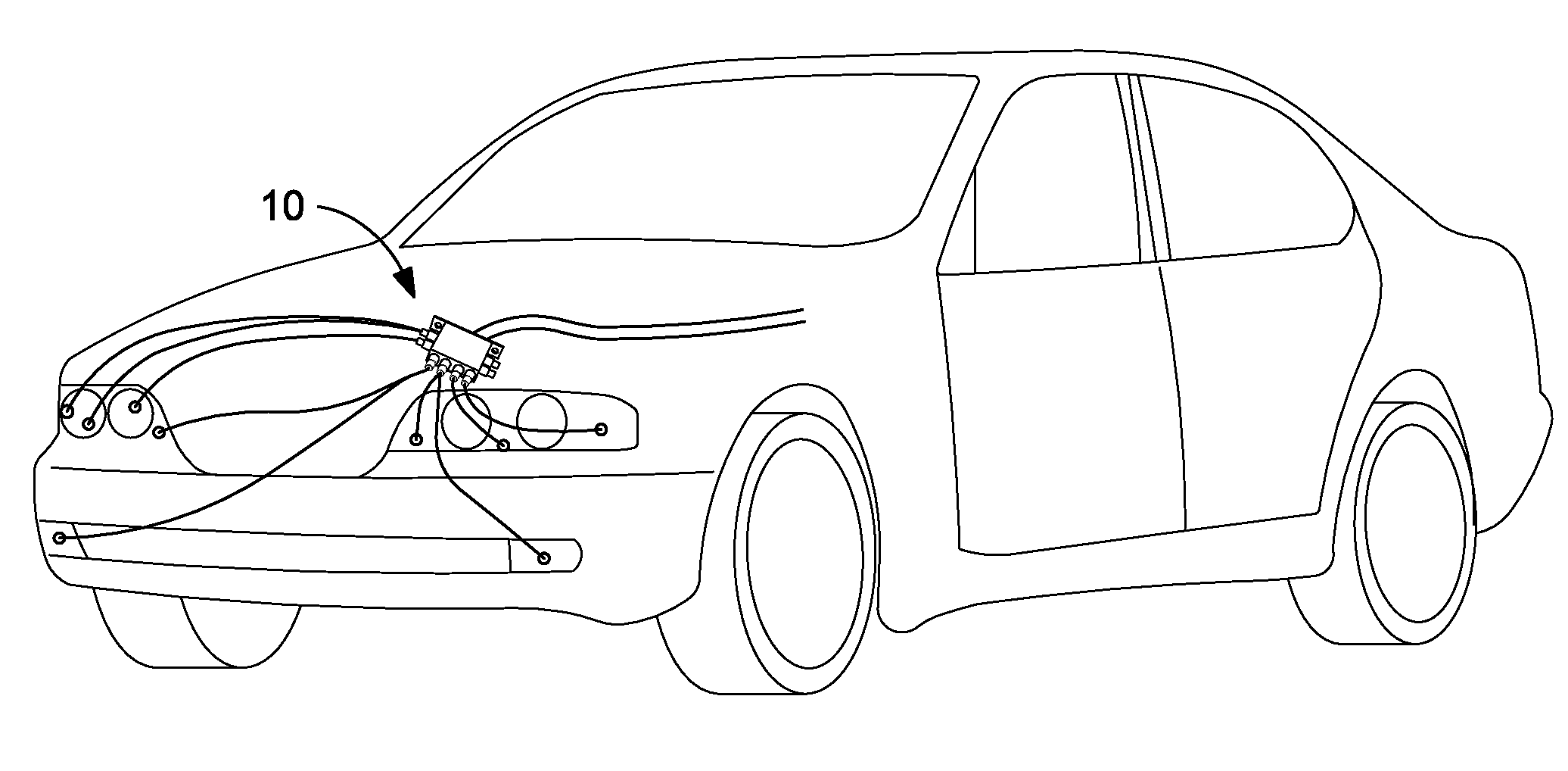
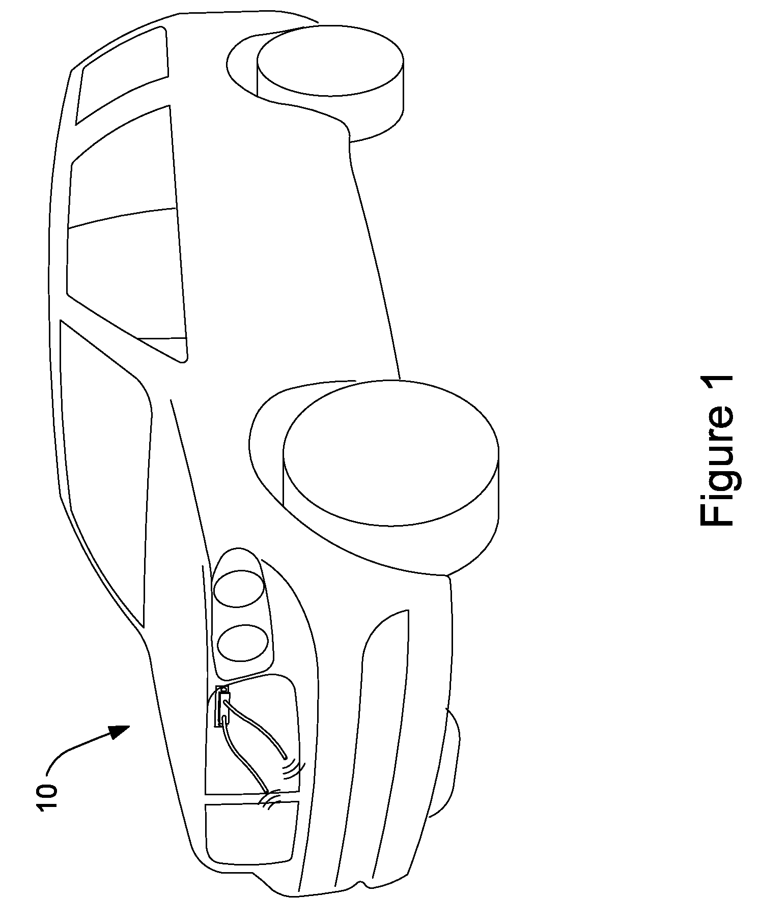
A concealed light detection and ranging system (LIDAR) for detecting, confusing, and jamming external laser, radar, infrared and other varieties of velocity and position detectors. The LIDAR mounts in numerous different locations on a vehicle such as the brake light, grill, door handle, etc. By utilizing a plethora of locations on the vehicle to receive and transmit light signals, the LIDAR allows generated light pulses to be carried by a network of fiber optic cables to the front, rear, top and sides of the vehicle. This ubiquitous positioning of the LIDAR on the vehicle allows for efficient reception and emission of light pulses to detect and / or, jam LIDAR guns, parking sensors, and proximity sensors without the need for the electronics to be exposed or mounted in the actual reception and transmission locations. When configured to detect lasers, the LIDAR further may include a laser receiver and pulse shaping device.

Description

CROSS-REFERENCE TO RELATED APPLICATIONS[0001]The present Utility patent application is a continuation-in-part and claims priority benefit of the U.S. Utility patent application Ser. No. 12 / 779,918 and entitled “Concealed Light Detection and Ranging System”, filed on May 13, 2010 now abandoned under 35 USC 111(a). The contents of this related utility patent application are incorporated herein by reference for all purposes to the extent that such subject matter is not inconsistent herewith or limiting hereof.FEDERALLY SPONSORED RESEARCH OR DEVELOPMENT[0002]Not applicable.REFERENCE TO SEQUENCE LISTING, A TABLE, OR A COMPUTER LISTING APPENDIX[0003]Not applicable.COPYRIGHT NOTICE[0004]A portion of the disclosure of this patent document contains material that is subject to copyright protection. The copyright owner has no objection to the facsimile reproduction by anyone of the patent document or patent disclosure as it appears in the Patent and Trademark Office, patent file or records, bu...

Claims


Application Information

Patent Timeline
Patent Type & Authority Patents(United States)
IPC IPC(8): G01C3/08G01S7/48G01S7/481G01S7/495
CPCG01S7/4806G01S7/4818G01S7/495
Inventor VOGT, LIONEL D.PAYNE, KENNETH E.FORTINBERRY, JARRODFARRISH, PHILIP
Owner LASER LIONS
Learn More