Substrate treatment installation

Inactive Publication Date: 2015-07-07
VON ARDENNE ANLAGENTECHNIK GMBH
View PDF11 Cites 206 Cited by
  • Summary
  • Abstract
  • Description
  • Claims
  • Application Information

AI Technical Summary

Benefits of technology

[0015]It may, however, also be expedient to insert further plate strips between the two plates, in order to further increase the strength of the housing, as will further be described below with the aid of an exemplary embodiment. In this way, a plurality of channels delimited from one another are then provided between the two parallel plates, and may for example respectively be used to receive a rod-shaped lamp.
[0016]As already indicated above, it may be advantageous for the housing to extend through at least one wall of t

Problems solved by technology

There are many examples—such as photoresists to be exposed on a substrate—in which a combination of a plurality of exposure fields necessarily leads to a

Method used


Image

  • Substrate treatment installation
  • Substrate treatment installation
  • Substrate treatment installation

Examples


Embodiment Construction

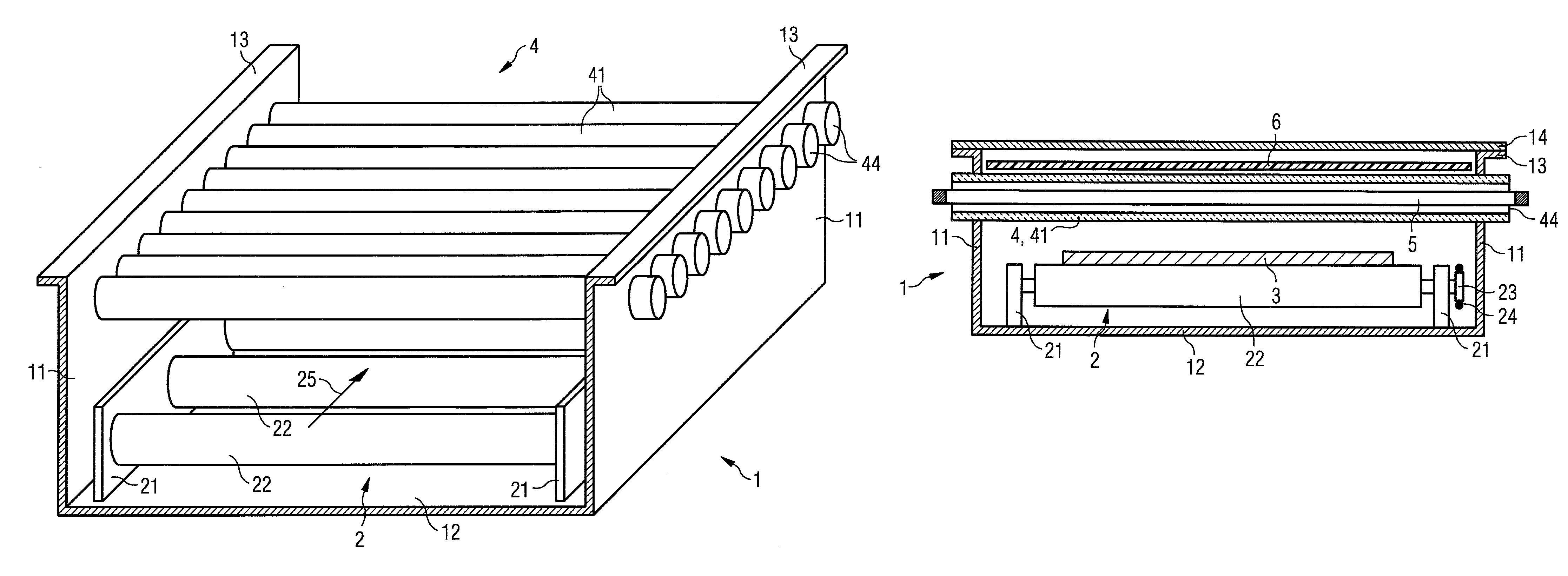
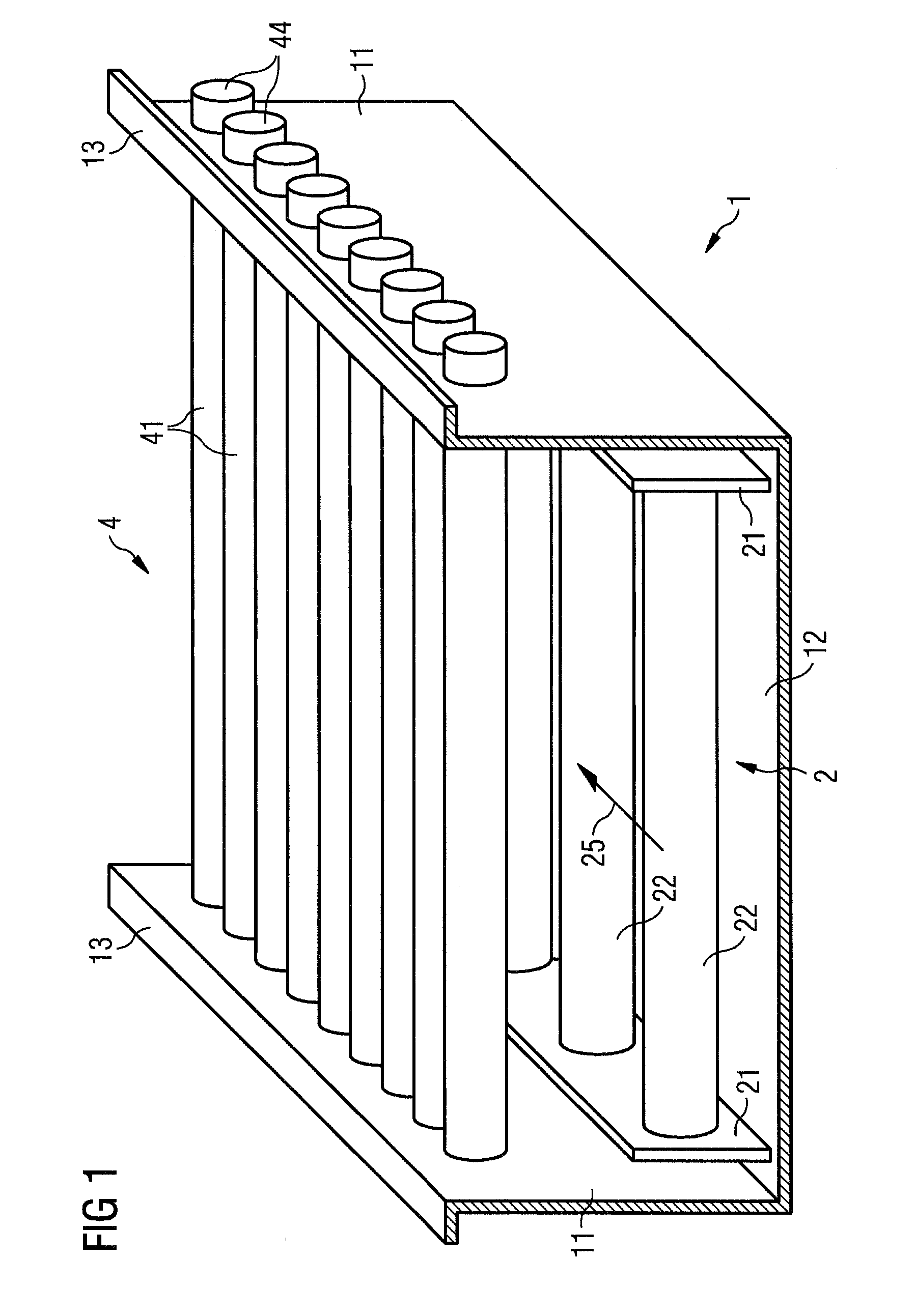
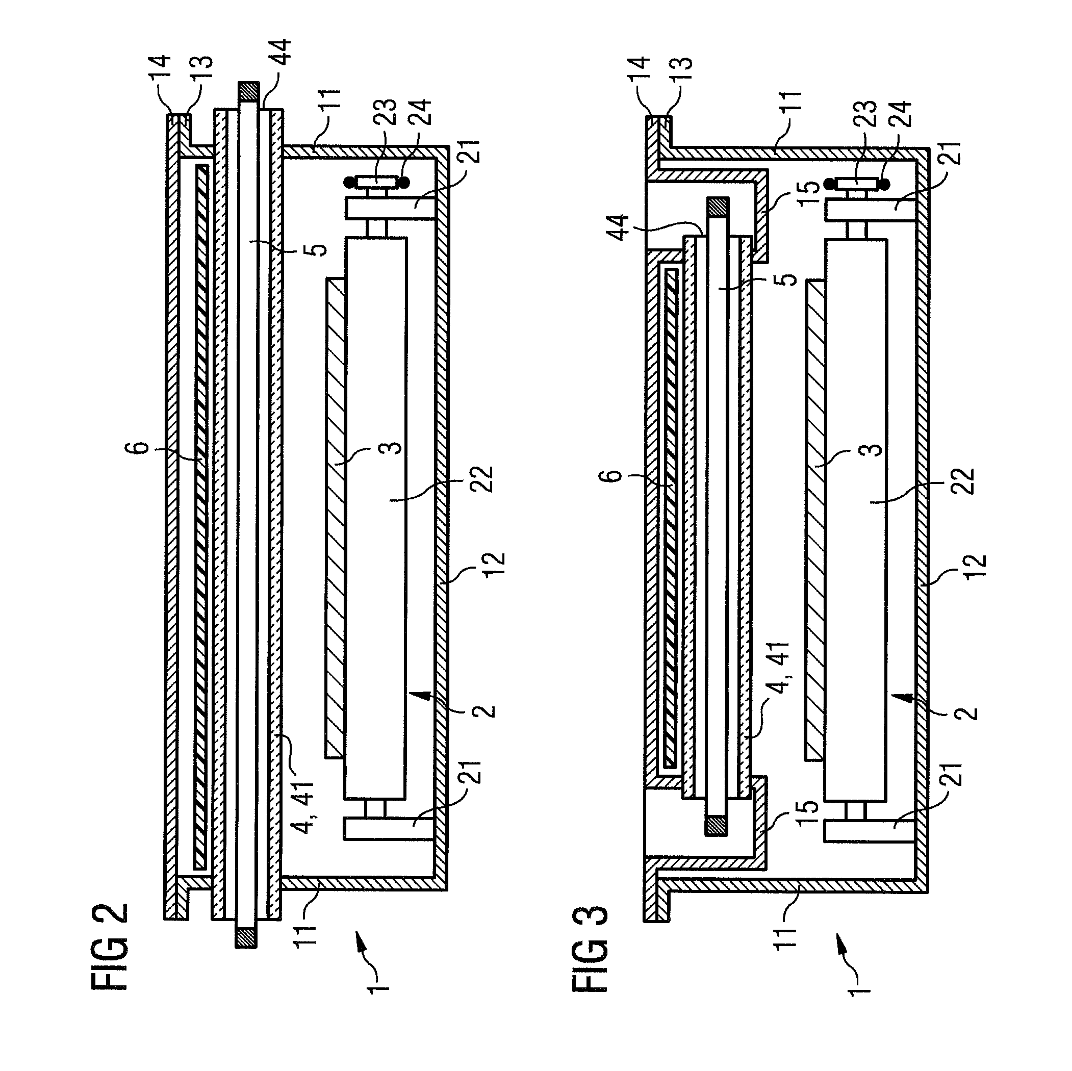
[0031]FIG. 1 shows a partial view of an installation chamber 1, which is part of a substrate treatment installation for the vacuum treatment of plate-shaped substrates. The installation chamber 1 comprises side walls 11, a bottom 12 and flanges 13, on which a cover (not represented here) can be placed so that the installation chamber 1 can be closed by the cover. A transport device 2 for the substrates 3 is arranged in the installation chamber 1. The transport device 2 is formed by an arrangement of transport rolls 22, which are arranged in a horizontal plane, are rotatably mounted in two bearing banks 21 and driveable, and on which the substrates to be treated are placed and moved in a transport direction 25 through the substrate treatment installation.

[0032]A section of the substrate treatment installation is shown, in which section the substrates are subjected to treatment by light. To this end, a lamp array is arranged in a plane above the transport device 2, which lamp array is...


PUM


Abstract

A substrate treatment installation includes an installation chamber and a light source for the exposure of substrates to light. The light source is arranged in the interior of the substrate treatment installation and includes at least one discharge lamp arranged in a housing, which is permeable to light at least in sections and has a vacuum-tight cavity for accommodating the lamp, and also at least one reflector element arranged in spatial proximity to the at least one lamp and having an electrical connection.

Description

CROSS REFERENCE TO RELATED APPLICATIONS[0001]This application is a national stage filing under section 371 of International Application No. PCT / EP2012 / 057765, filed on Apr. 27, 2012, and published in German on Nov. 1, 2012, as WO 2012 / 146715 A1 and claims priority of German applications No. 10 2011 100 098.8 filed on Apr. 29, 2011, and No. 10 2011 081 749.2 filed on Aug. 29, 2011, the entire disclosure of these applications being hereby incorporated herein by reference.BACKGROUND ART[0002]The invention relates to a substrate treatment installation.[0003]If exposure or heat-treatment processes are intended to be carried out with the aid of pulsed gas discharge lamps (flash lamps) on large substrates, that is to say for example with a surface area of about 1 m2 or more, this can be achieved in two ways: one is for a single lamp (or a small array of lamps which cover only a part of the substrate) to be moved relative to the substrate so that the entire substrate can ultimately be expos...

Claims


Application Information

Patent Timeline
IPC IPC(8): H01J1/02H01J37/32H01L21/67H01J7/26
CPCH01J37/32522H01L21/67115H01J7/26
Inventor GROSS, HARALDZSCHIESCHANG, ERWIN
Owner VON ARDENNE ANLAGENTECHNIK GMBH
Why Eureka
Try Eureka