Stirling engine with flapping wing for an emission-free aircraft

a technology of engine and wing, which is applied in the direction of propellers, rotorcraft, air transportation, etc., can solve the problems of high cost of solar cells, insufficient battery material for operating an emission-free airplane, etc., and achieve the effect of quick cooling or heating of working gas

Inactive Publication Date: 2015-07-14
AIRBUS DEFENCE & SPACE
View PDF43 Cites 8 Cited by
  • Summary
  • Abstract
  • Description
  • Claims
  • Application Information

AI Technical Summary

Benefits of technology

[0012]A “flat-plate Stirling engine” is a Stirling engine that includes a displacer with intermittent control. The displacer operates with very low temperature difference, which is also due to the fact that the system of the flat plate has a larger heat transfer surface in proportion to the working volume. A surface also referred to as front wall can be heated, according to the present invention, in particular by solar insolation. Flat-plate Stirling engines are suitable for converting thermal energy, which is provided by the solar thermal radiation, into kinetic energy. Flat-plate Stirling engines can be driven at low temperature differences, e.g., at a temperature difference of approximately 15°. Due to their active principle, flat-plate Stirling engines can be realized with relatively light components. Due to the use of the solar thermal radiation as a heat source, which is unavoidable for the operation of the flat-plate Stirling engine, an emission-free drive, i.e., a drive with reduced CO2 discharge is possible.
[0020]The alignment of the top to the solar thermal radiation results during flight operation, since the top always points upwards and thus in the direction of the solar insolation. The solar insolation, to put it simply, causes a heating of the working gas in the region above the displacer, whereby the working gas expands and presses the working piston outwards. Subsequently, a cooling takes place and thus a contraction of the working gas in the upper region and a new movement of the working piston occurs, whereupon a new step of heating and expanding begins again. In this manner, the displacer transports the working gas to and fro between the hot top and the cold underside in order to achieve a quick cooling or heating of the working gas.

Problems solved by technology

With the use of electric motors, however, batteries necessary for operating an emission-free airplane are not yet available according to the known prior art.
However, the solar cells are associated with high costs.

Method used


Image

  • Stirling engine with flapping wing for an emission-free aircraft
  • Stirling engine with flapping wing for an emission-free aircraft
  • Stirling engine with flapping wing for an emission-free aircraft

Examples


Embodiment Construction

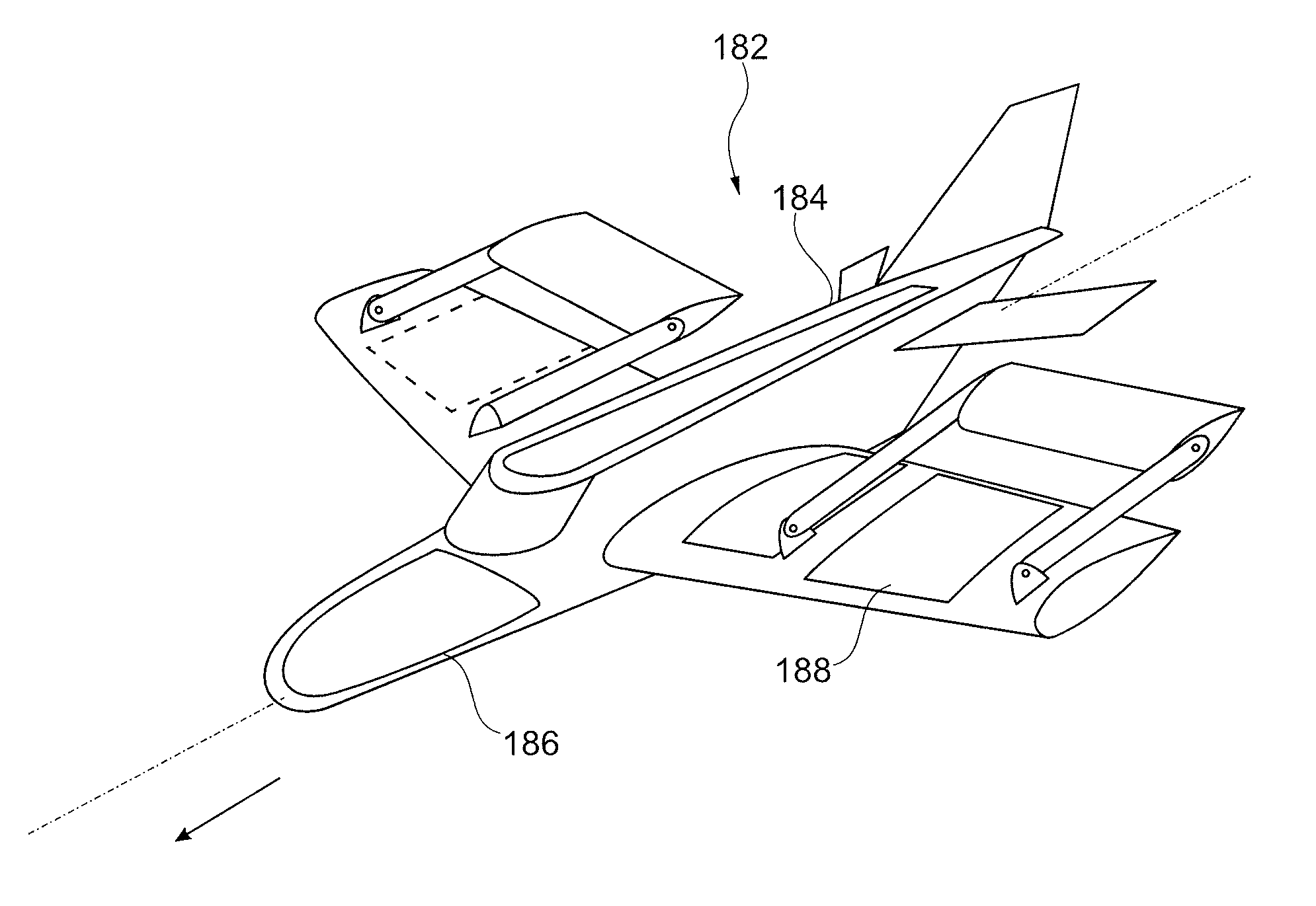
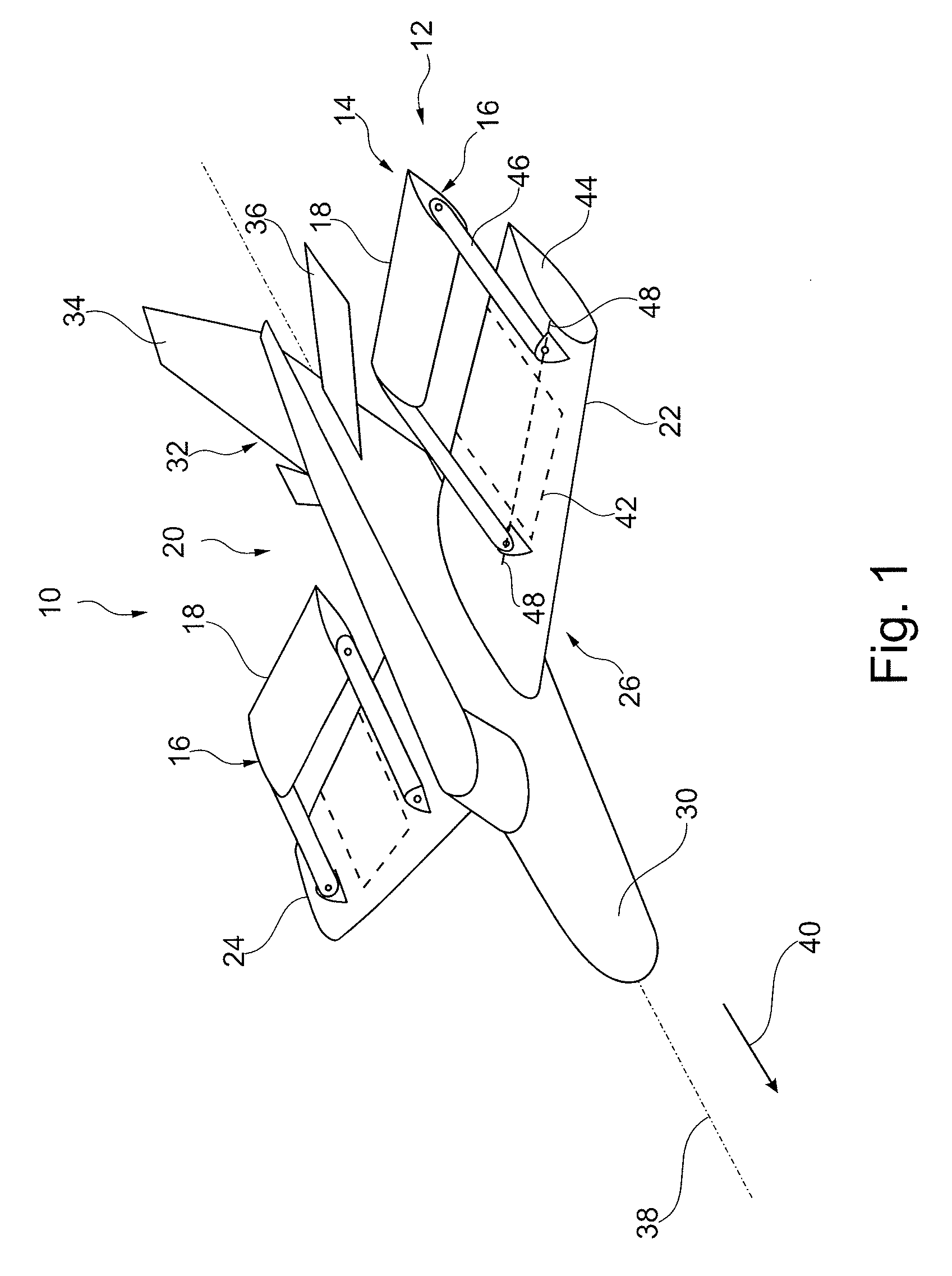
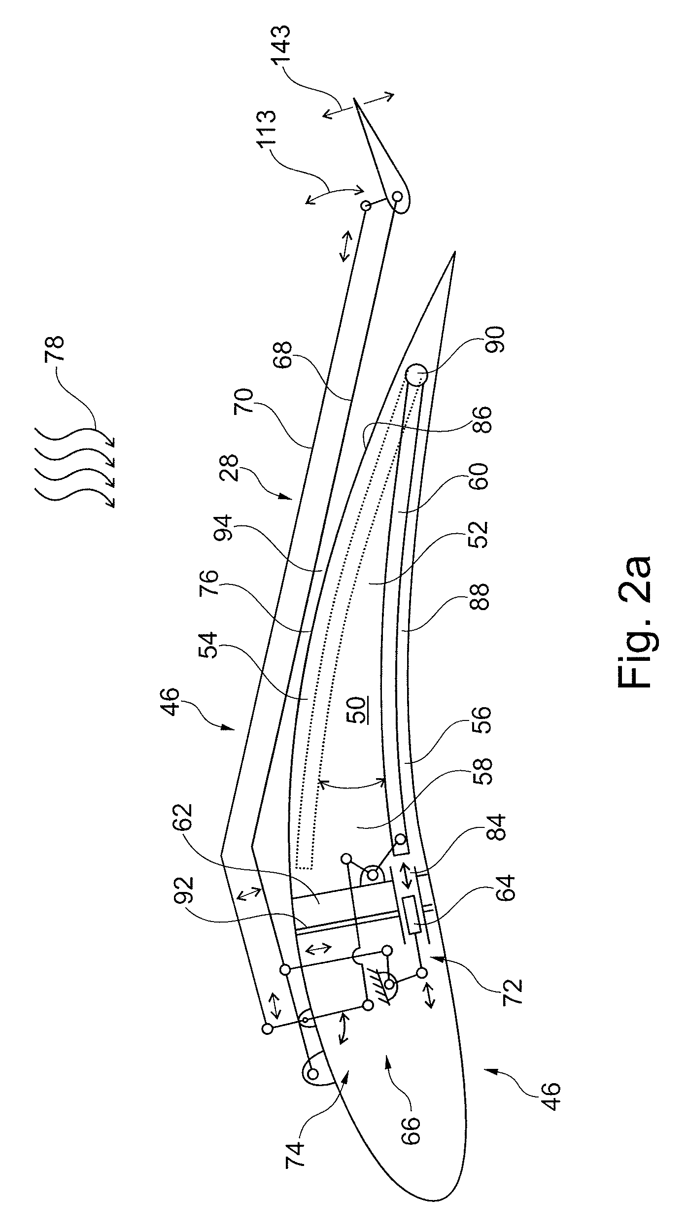
[0007]Embodiments of the invention are directed to an aircraft with an emission-free drive that includes a drive device for generating a thrust, a lift device for generating a lift, and a heat engine for converting thermal energy into kinetic energy for driving the drive device. The drive device has a flapping wing device for a thrust generation, with at least one flapping wing, which can pivot transverse to the flight direction. The flapping wing is held by a holding device so that it can pivot around a pivot axis running transverse to the flight direction. At least one flat-plate Stirling engine that can be driven by solar thermal radiation as a heat engine, which includes a displacer arranged in a movable manner in a working chamber with a changeable working volume, and a working piston connected to the working chamber for changing the working volume. The working piston is coupled to a support device of the holding device via a primary transmission device in such a way that a lin...


PUM


Abstract

Aircraft with an emission-free drive and method for emission-free driving of an aircraft. The aircraft includes a drive device, having a flapping wing device, structured and arranged to generate thrust, a lift device structured and arranged to generate lift, and a heat engine, having at least one flat-plate Stirling engine drivable by solar thermal radiation, structured and arranged to convert thermal energy into kinetic energy to drive the drive device. The flapping wing device includes at least one flapping wing, which is pivotable transverse to a flight direction.

Description

CROSS-REFERENCE TO RELATED APPLICATIONS[0001]The present application claims priority under 35 U.S.C. §119(a) of German Patent Application No. 10 2011 122 071.6 filed Dec. 22, 2011, the disclosure of which is expressly incorporated by reference herein in its entirety.BACKGROUND OF THE INVENTION[0002]1. Field of the Invention[0003]The present invention relates to emission-free flying, to an aircraft with an emission-free drive, and to a method for driving an aircraft.[0004]2. Discussion of Background Information[0005]Aircraft, e.g., airplanes, have a drive device, e.g., one or more propellers, for the forward movement of the aircraft. The drive takes place by an internal combustion engine. Moreover, turbines can also be used as a drive device, which is likewise based on the combustion of fuel. Due to the generally acknowledged topic of global warming, however, consideration is increasingly being given to operating an airplane emission-free as far as possible, or at least with a reduce...

Claims


Application Information

Patent Timeline
Patent Type & Authority Patents(United States)
IPC IPC(8): B64C33/00F01D5/12B64C39/00B64D27/02B64D27/24
CPCF01D5/12B64C39/005B64D27/02B64D27/24Y02T50/62F01B23/02F02G1/043F02G1/055F02G2254/30F02G2270/30F02G2270/40F02G2270/42F02G2270/80F02G2280/00F02G2280/50Y02T50/60
Inventor SEIFERT, JOST
Owner AIRBUS DEFENCE & SPACE
Why Eureka
Try Eureka