Luminance boost method and system

a technology of luminance and boost method, which is applied in the field of methods and systems for adjusting the luminance of image display devices, can solve the problems of limited display backlight lifetime and other problems, and achieve the effects of improving the visibility of subtle image differences, good compromise, and enhancing the detection of subtle features

Active Publication Date: 2015-07-14
BARCO NV
View PDF3 Cites 2 Cited by
  • Summary
  • Abstract
  • Description
  • Claims
  • Application Information

AI Technical Summary

Benefits of technology

[0005]The present invention provides a system and method for improving the visibility of subtle image differences. The system and method provide two operating modes of a display, these being a normal mode and a boost mode. In the normal mode the display is configured to have a normal luminance level such that there is a good compromise between display lifetime and detectability of subtle features. For transmissive displays that use backlights, lifetime of the display is often limited by the display backlight lifetime. In case of emissive displays, display lifetime if often limited by the lifetime of the active emitting material (e.g., OLED material). In the boost mode, the display is for a short period of time set to a much higher luminance level such that subtle features can more easily be detected. For example, the luminance of the backlight is modified in case of transmissive displays and the luminance of the active emissive material is modified in the case of emissive displays.
[0010]The system and method, depending on its particular implementation, can overcome one or more problems associated with prior art systems. Lifetime can be maximized while at the same time maximizing detectability. Additionally or alternatively, the problems of eye adaptation correct medical calibration can be solved.
[0015]According to another aspect of the invention, the display settings are DICOM GSDF compliant at the first luminance setting, at the second luminance setting and during the adaptation period. In addition, the video content that is sent to the display panel may be modified following receipt of a request for improved visualization and prior to or at the moment of increasing the luminance of the display. For example, if the maximum video level of the display is 255 and the display is set to a lower level, such as 199, at the time the request for improved visualization is received, the video level may be increased (e.g., by way of contrast enhancement and adjusting other display parameters as will be understood by those skilled in the art) prior to increasing the luminance of the display. Thus, if a display shows an image that does not make use of the entire dynamic range that the display offers (e.g., the image sent to the display panel only contains gray levels 54 up to 220) then the image data can be modified such that the entire dynamic range of the display is used. This further improves visualization of the image.
[0019]The method may also provide a viewer with the ability to further increase luminance of the display. Accordingly, the method may further include receiving a request for improved visualization of the display operating at a second luminance setting with modified display parameters; increasing the luminance of at least part of the display from the second luminance setting to a third luminance setting; modifying the display parameters to correspond to the increased luminance such that the perceived difference in luminance between adjacent levels at the third luminance setting is greater than the perceived difference in luminance between adjacent levels at the second luminance setting; and continuously modifying the display parameters during an adaptation period to match an adaptation of a human eye to the change in luminance from the second luminance setting to the third luminance setting.

Problems solved by technology

For transmissive displays that use backlights, lifetime of the display is often limited by the display backlight lifetime.

Method used


Image

  • Luminance boost method and system
  • Luminance boost method and system
  • Luminance boost method and system

Examples


Embodiment Construction

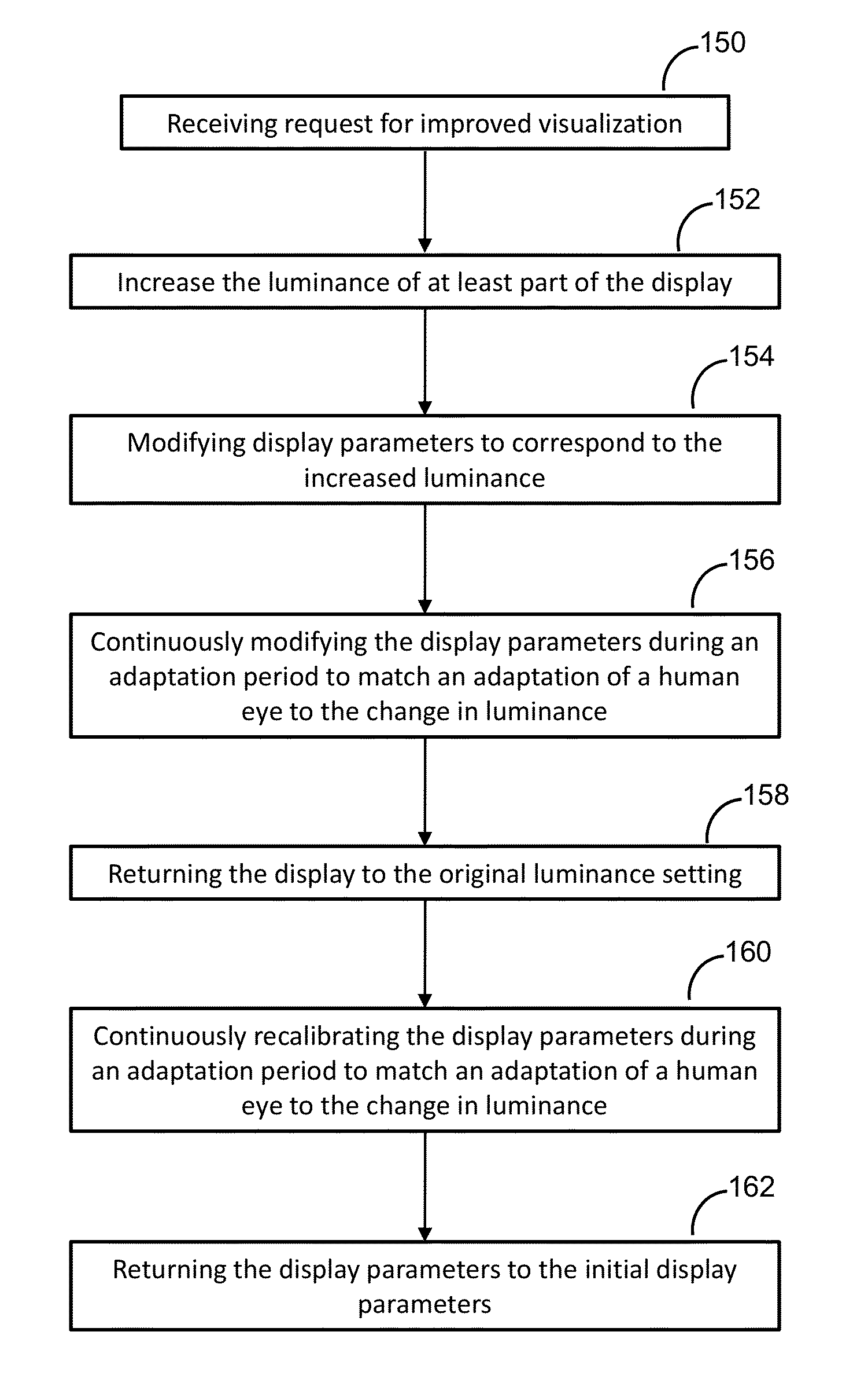
[0031]The present invention relates to a system and method providing the viewer with an increased ability to perceive subtleties in the displayed image without dramatically decreasing the lifetime of the display as would occur if the display were permanently set at a high luminance level.

[0032]For example, medical displays may need to achieve lifetimes (time to half of initial peak luminance) of 50,000 hours and more. To achieve such long lifetime, medical displays may be set to a luminance output much lower than the initially maximum achievable level. Consequently, clinicians are diagnosing patients using displays operating at less than maximum luminance. This makes it more difficult for those clinicians to see subtle differences in images and, thus, making a diagnosis takes more time and it is more difficult to determine the correct diagnosis for their patients.

[0033]As used herein, the term “display” is not intended to be limited to any particular types of displays, and includes ...


PUM


Abstract

A system and method for increasing perceived contrast in a medical display is provided. The method involves temporarily increasing luminance output of at least part of a display in response to a received request for improved visualization. To compensate for the change in luminance especially while the viewer's eyes adapt to the change in luminance, the method includes continuously modifying the display parameters especially during an adaptation period to match an adaptation of the viewer's eyes. The modified parameters at any given may correlate to the degree of adaptation by the viewer's eyes to the change. After a period of time, the display may be returned to its normal operating luminance and corresponding settings, which may be selected to maximize the lifetime of the display.

Description

RELATED APPLICATION[0001]This application is a national phase application of International Application No. PCT / US2011 / 040344 filed Jun. 14, 2011, which claims priority from U.S. Application No. 61 / 354,313, filed Jun. 14, 2010.FIELD OF THE INVENTION[0002]The present invention relates generally to image display devices, and particularly to methods and systems for adjusting the luminance of image display devices.BACKGROUND[0003]When using imaging devices for diagnostic purposes, clinicians often are looking for very subtle image features that can indicate the presence of disease. It is well known that brighter displays provide clinicians with the ability to see more subtle features as compared to darker displays having the same physical contrast. It is for this reason that medical displays in particular are typically designed to be as bright as possible.[0004]Of course, it is also well known that higher luminance results in higher heat levels which speeds up degradation and decreases e...

Claims


Application Information

Patent Timeline
Patent Type & Authority Patents(United States)
IPC IPC(8): G09G5/10G09G3/34
CPCG09G5/10G09G3/3406G09G2320/0276G09G2320/041G09G2320/043G09G2320/066G09G2320/0613G09G2320/0626G09G2320/0653G09G2320/0673G09G2320/0693G09G2330/022G09G3/3208G09G2320/0233
Inventor KIMPE, TOMXTHONA, ALBERT
Owner BARCO NV
Why Eureka
Try Eureka