
Multi-force resistant mechanical joint

a technology of mechanical joints and force resistance, applied in the direction of rod connections, fastening means, toys, etc., can solve the problems of low strength, difficult connection, etc., and achieve the effect of tightly retaining dimensional accuracy and simple connection and separation

Inactive Publication Date: 2015-07-21
SHARMAN CHARLES SCOTT
View PDF24 Cites 13 Cited by
  • Summary
  • Abstract
  • Description
  • Claims
  • Application Information

AI Technical Summary

Benefits of technology

The invention provides a mechanical joint that is small, strong, and can resist any force in multiple directions. It is easy to connect and disconnect, remains stable, and can be rotated in precise increments.

Problems solved by technology

While tiny, the Lego® mechanical joint suffers from one primary drawback: low strength.
Increasing the joint strength makes connecting more difficult.
Firstly, because of alignment and dexterity, connecting and separating can be difficult, particularly when the connecting structures are smaller than a finger.
Secondly, because of an over-sized hole for the pin, wiggle remains after the joint has been formed, losing some dimensional accuracy.

Method used


Image

  • Multi-force resistant mechanical joint
  • Multi-force resistant mechanical joint
  • Multi-force resistant mechanical joint

Examples


Embodiment Construction

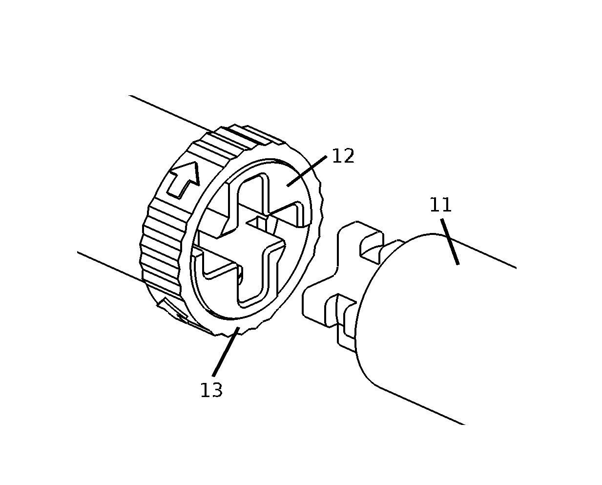
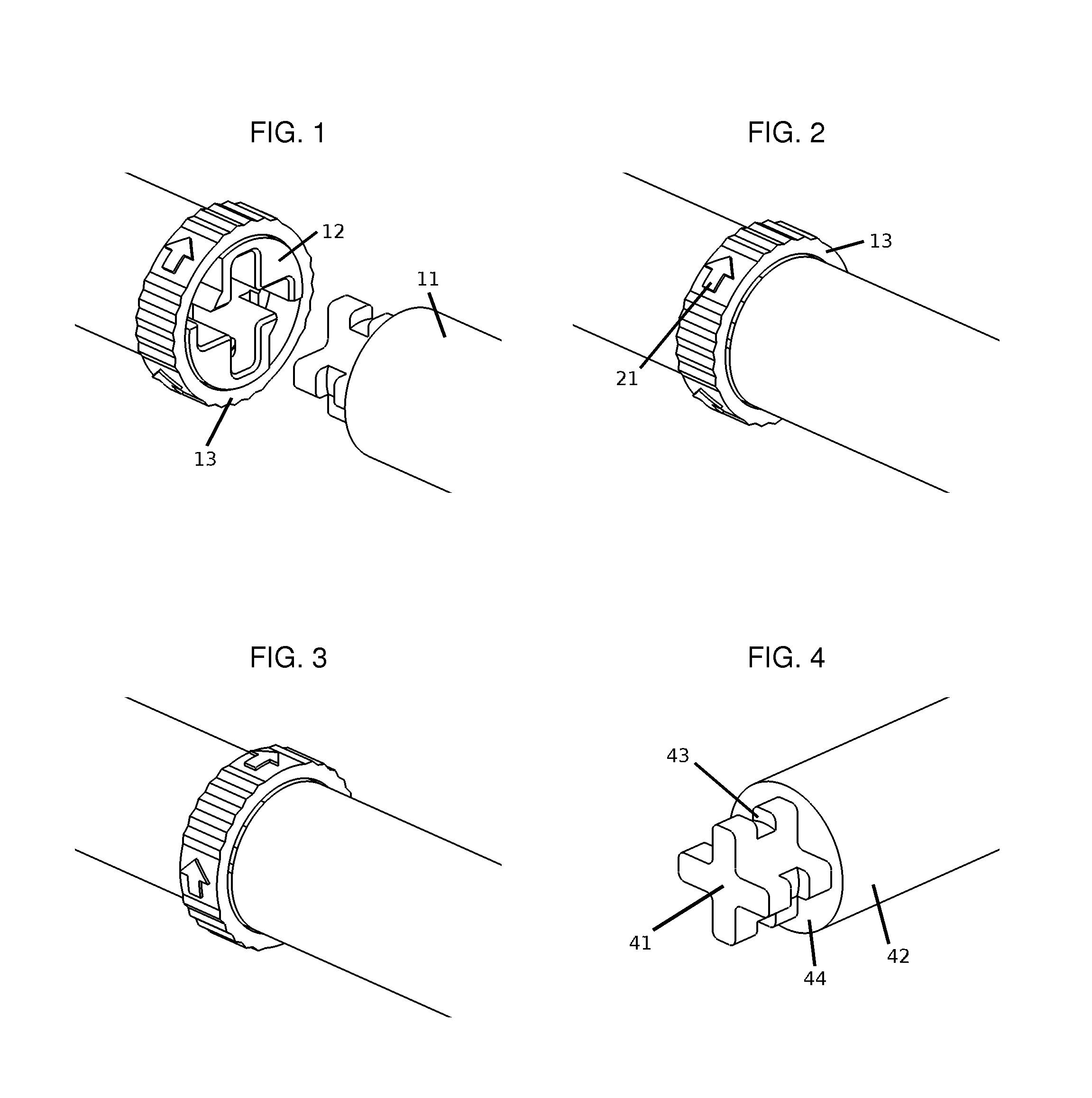
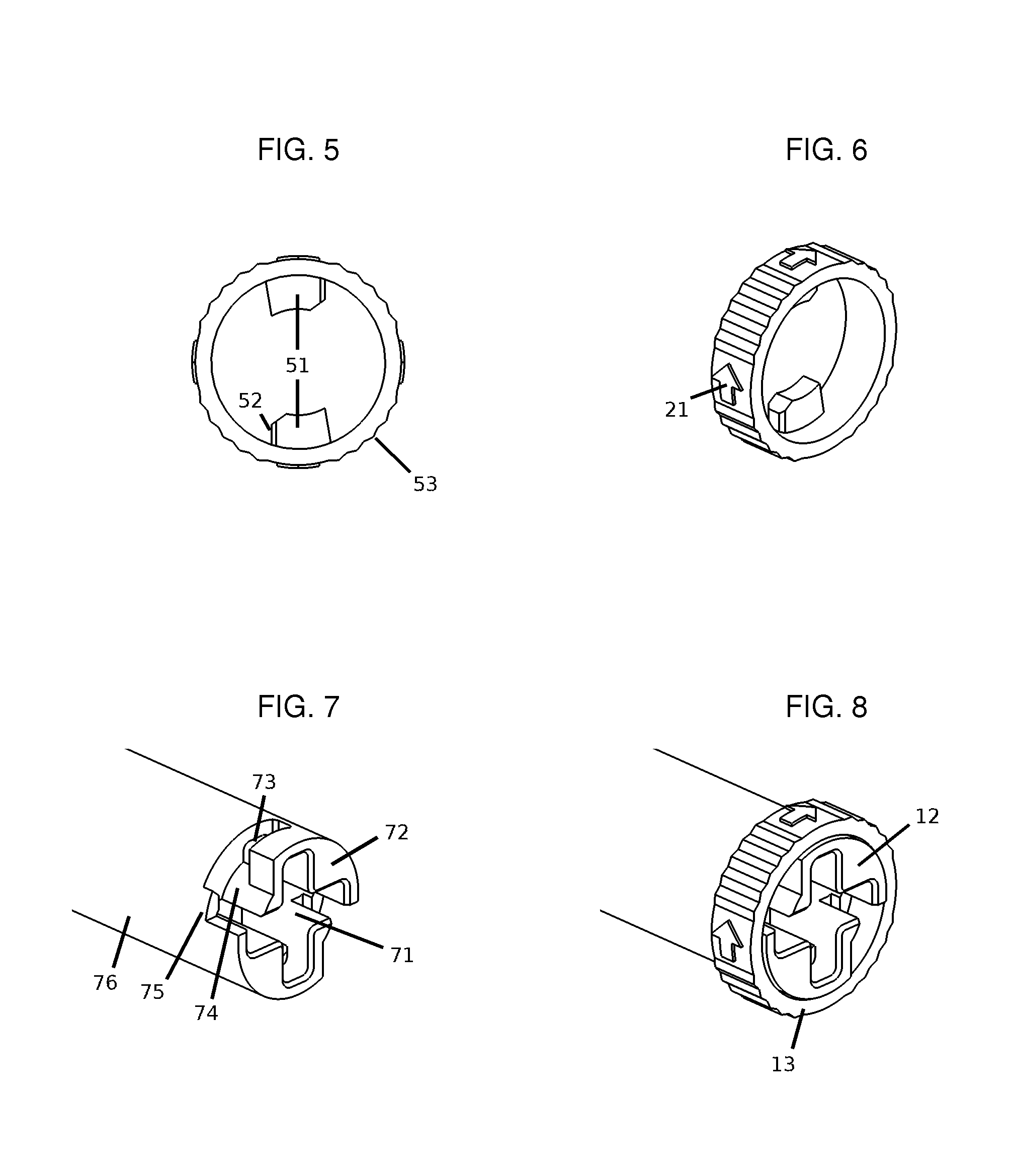
[0023]Referring now to the drawings, FIGS. 1-3 are a sequence of 3 frames, showing the joint connecting process for one embodiment. FIG. 1 begins with the joint apart. The male-side of the joint 11 is comprised of a single element. The female-side of the joint is comprised of two elements, a receptacle 12 and a tabbed ring 13. The tabbed ring is snapped onto the receptacle during factory assembly and cannot pop off.

[0024]To connect, the male-side slides into the female-side, FIG. 2. Then, the tabbed ring 13 rotates a partial turn in the direction of the tabbed ring's arrow 21 to complete the joint, FIG. 3. Once complete, the joint will not separate under compression, tension, shear, or torsional stresses between the male-side and female-side. Reversing FIGS. 1-3 easily separates the joint.

[0025]FIG. 4 shows one embodiment of the male-side of the joint. The male-side is comprised of a single element. The element visually consists of two sections: a plug 41 and a male section 42. The ...


PUM


Abstract

A mechanical joint that resists any direction of imposed force and can be connected in set rotational increments is comprised of three elements: a plug attached to the male-side of the joint, and a receptacle and a tabbed ring attached to the female-side side of the joint. The male-side and female-side are connected by sliding the plug into the receptacle and rotating the tabbed ring a partial turn. Reversing the connecting steps separates the joint.

Description

CROSS-REFERENCE TO RELATED APPLICATIONS[0001]Not ApplicableSTATEMENT REGARDING FEDERALLY SPONSORED RESEARCH OR DEVELOPMENT[0002]Not ApplicableREFERENCE TO SEQUENCE LISTING, A TABLE, OR A COMPUTER PROGRAM LISTING COMPACT DISC APPENDIX[0003]Not ApplicableBACKGROUND OF THE INVENTION[0004]Mechanical joints and hand-manipulated mechanical joints find uses across multiple industries and consumer applications.[0005]Our first introduction to mechanical joints usually comes in children's toys. Christiansen's patent (3,005,282), the Lego® mechanical joint, for example, is a friction-based joint. To connect the joint, the user overcomes friction while sliding the pieces together. That same friction holds the pieces together. While tiny, the Lego® mechanical joint suffers from one primary drawback: low strength. In tension, the separation force is roughly equal to the connecting force. Increasing the joint strength makes connecting more difficult.[0006]The cotter pin, similar to Smith's patent ...

Claims


Application Information

Patent Timeline
Patent Type & Authority Patents(United States)
IPC IPC(8): B25G3/16F16B7/20F16B21/04
CPCF16B21/04A63H33/067
Inventor SHARMAN, CHARLES SCOTT
Owner SHARMAN CHARLES SCOTT
Learn More