
Mobile device and charging apparatus

a technology of mobile devices and charging devices, applied in the directions of mobile unit charging stations, transportation and packaging, and battery arrangements, etc., can solve the problem of superfluous operation

Active Publication Date: 2015-07-28
SONY CORP
View PDF5 Cites 17 Cited by
  • Summary
  • Abstract
  • Description
  • Claims
  • Application Information

AI Technical Summary

Benefits of technology

The patent text discusses the problem of mobile devices having a rechargeable battery that can become depleted quickly if the user does not use them shortly after charging. To address this issue, the text suggests a method where a transmitter coil moves back and forth to check the charge state of the battery. However, this method may not always be efficient and may increase power expenditure. The technical effect of this patent is to provide a method to keep the battery at a full charge and conserve power by minimizing the movement of the transmitter coil.

Problems solved by technology

Also, even if a power transmitting apparatus initiates a power transmitting operation as disclosed in PTL 2, the operation will be superfluous if the rechargeable battery provided in the power receiving apparatus is at a sufficient charge level.

Method used


Image

  • Mobile device and charging apparatus
  • Mobile device and charging apparatus
  • Mobile device and charging apparatus

Examples


first embodiment (

1-1. First embodiment (example of charging a rechargeable battery in a battery pack inserted into a mobile device)

1-2. Modification of first embodiment (example of issuing instructions to start recharging by operational input from the user)

second embodiment (

2-1. Second embodiment (example of charging rechargeable batteries in battery packs inserted into a plurality of mobile devices)

2-2. Modification of second embodiment (example of setting recharge priority order by operational input from the user)

3. Modification of third embodiment (example of charging a rechargeable battery in another mobile device when the charge level of a rechargeable battery exceeds a threshold value)

4. Modification of fourth embodiment (example of setting rechargeable battery charge levels and recharge priority order)

5-1. First modification

5-2. Second modification

first embodiment

1-1. First Embodiment

Example of Charging a Rechargeable Battery in a Battery Pack Inserted into a Mobile Device

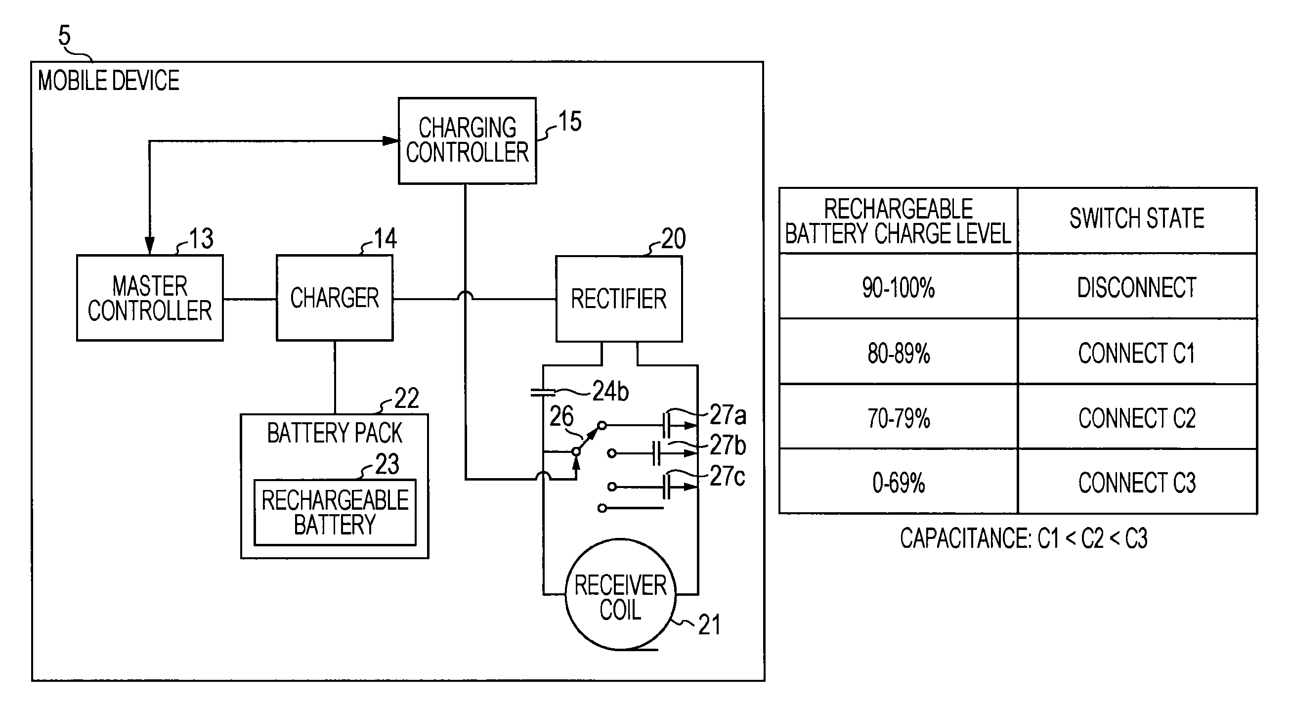
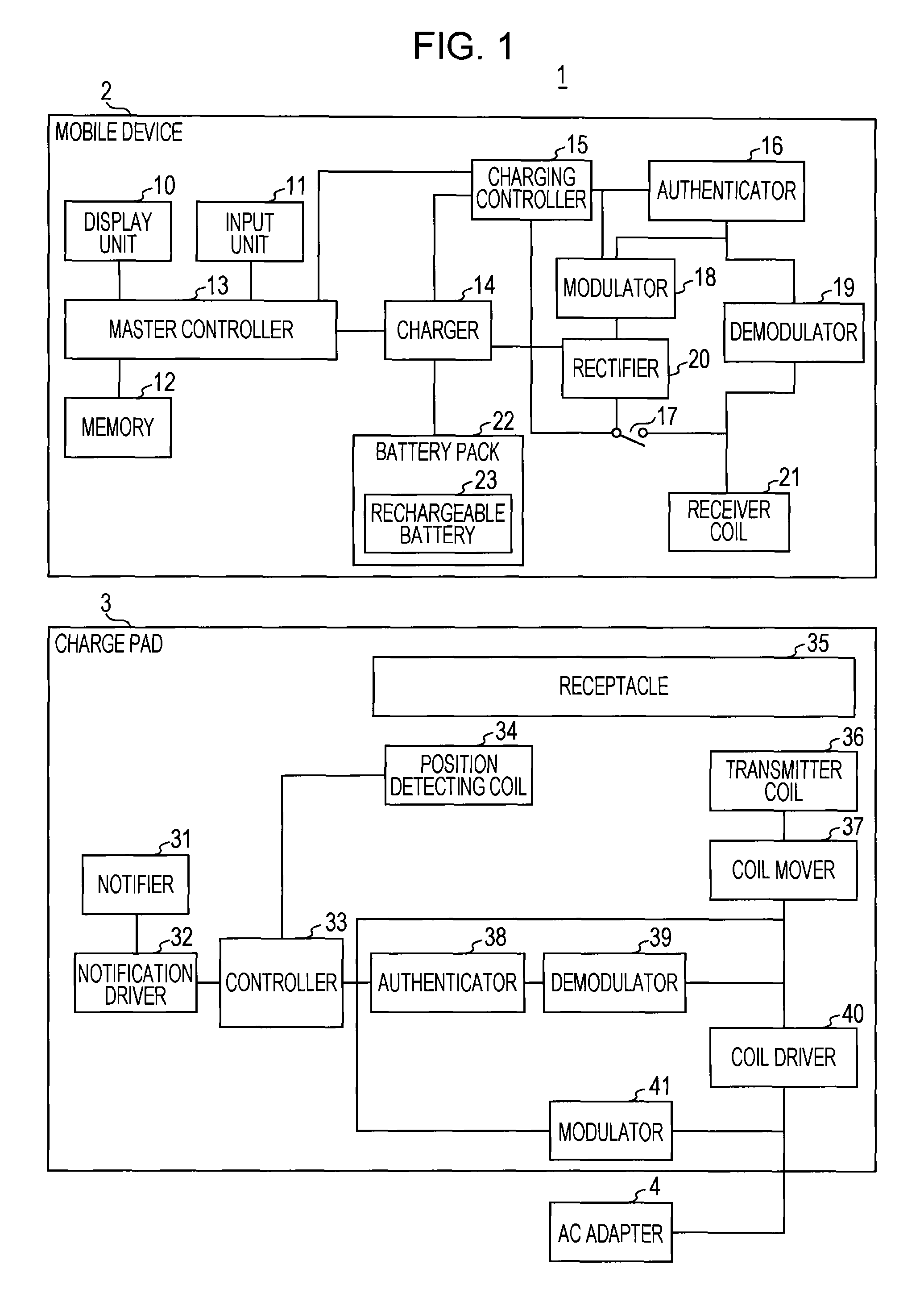
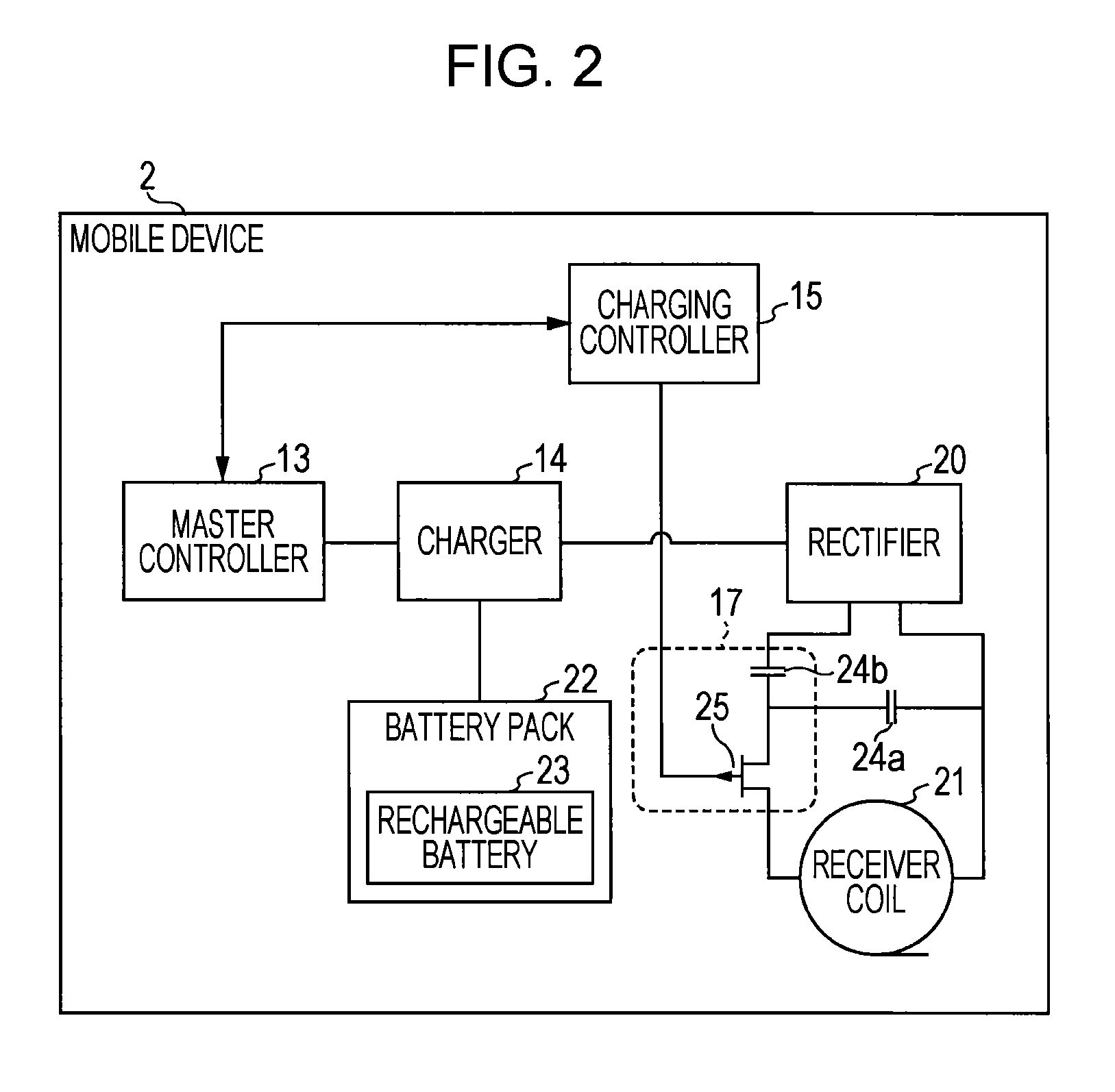
[0035]Hereinafter, a first embodiment of the present disclosure will be described with reference to FIGS. 1 to 5. In the present embodiment, an example will be described wherein a charge pad 3 wirelessly charges a rechargeable battery 23 in a battery pack 22 inserted into a mobile device 2, which is used as an information processing device such as a mobile phone or ebook reader, for example. The mobile device 2 adopts a moving coil technique and realizes a charge instructing method that issues instructions to start charging a rechargeable battery to a charge pad 3, which wirelessly charges a rechargeable battery 23 in a mobile device 2 in which a change of capacitance is detected. This charge instructing method is realized by a computer in the mobile device 2 executing a program, with internal blocks operating in coordination therewith. First, an exemplary configuration of ...


PUM


Abstract

When the charge level of a fully-charged rechargeable battery decreases due to quiescent power drain, in order to recharge it is necessary for the user to pick up and again place the mobile device in which the rechargeable battery is inserted onto a charging apparatus and issue instructions to start recharging. To address this issue, a charging controller applies control to disconnect a capacitor from a receiver coil with a switch in the case where the charge level of a rechargeable battery is equal to or greater than a given threshold value, and additionally applies control to connect the capacitor to the receiver coil with the switch in the case where the charge level of the rechargeable battery is less than the threshold value.

Description

CROSS-REFERENCE TO RELATED APPLICATIONS[0001]The present application is based on and claims the benefit of priority to U.S. Application No. 61 / 577,697, filed Dec. 20, 2011, the entire contents of which are incorporated herein by reference.TECHNICAL FIELD[0002]The present disclosure relates to a mobile device that issues instructions to start charging to a charging apparatus which wirelessly charges a rechargeable battery, and also relates to a charging apparatus.BACKGROUND ART[0003]Hitherto, there have been proposed a charging apparatus able to charge a rechargeable battery in a battery pack inserted into a mobile phone or other information processing device by using a standardized wireless power format.[0004]At this point, exemplary operation of a conventional charging apparatus will be described with reference to FIG. 17.[0005]FIG. 17 illustrates how a conventional charge pad 102 charges a mobile device 101.[0006]A flat charge pad 102 used as a charging apparatus is provided with ...

Claims


Application Information

Patent Timeline
Patent Type & Authority Patents(United States)
IPC IPC(8): H02J7/00H02J7/02H02J5/00
CPCH02J7/025H02J7/0027H02J7/0044H02J5/005H02J50/90H02J7/0013H02J50/12H02J50/40
Inventor SAKAI, DAISUKESUZUKI, KUNIHARUSUZUKI, KATSUYA
Owner SONY CORP
Learn More