Transceiver front-end

a transceiver and front-end technology, applied in powerline communication systems, powerline communication systems, electrical equipment, etc., can solve the problems of increasing the size of the transceiver implementation, affecting the transmission of signals, and affecting the operation of the transceiver, so as to avoid power loss due to a dummy load, avoid the matching of dummy loads to antenna impedance, and simple and efficient area

Active Publication Date: 2015-07-28
TELEFON AB LM ERICSSON (PUBL)
View PDF7 Cites 46 Cited by
  • Summary
  • Abstract
  • Description
  • Claims
  • Application Information

AI Technical Summary

Benefits of technology

[0013]It is an object of some embodiments to obviate at least some of the above disadvantages and to provide improved integrated solutions that provide isolation between a transmitter and a receiver.
[0047]Some embodiments provide solutions for isolation between a transmitter and a receiver that are simple and area efficient (e.g., two transformers and two or more filter arrangements). Furthermore, the solutions according to some embodiments provide isolation while having low power consumption.

Problems solved by technology

Example reasons include that as much of the received energy as possible should be transferred to the receiver for optimal receiver performance and that received signals occurring at the transmitter output may cause interference to the signal to be transmitted.
A drawback with duplexers is that they are typically expensive.
They are also bulky which increases the size of a transceiver implementation.
These problems are becoming more pronounced as the number of frequency bands to be supported by a communication device is increased.
If the antenna impedance is complex (inductive or capacitive) and / or varies over time (e.g., due to frequency changes and / or changing antenna surroundings), implementation of a perfect cancellation becomes cumbersome.
Furthermore, at least 3 dB of the power of receive and transmit signals will be lost in the dummy load.
Similarly as described above, a drawback of this solution is that the balance network needs to track impedance changes in the antenna during operation to enable sufficient isolation.
Thus, the implementation is sensitive and complex.
A further drawback of this solution is that at least 3 dB of the power of receive and transmit signals will be lost due to the matched impedance of the balance network.

Method used


Image

  • Transceiver front-end
  • Transceiver front-end
  • Transceiver front-end

Examples


Embodiment Construction

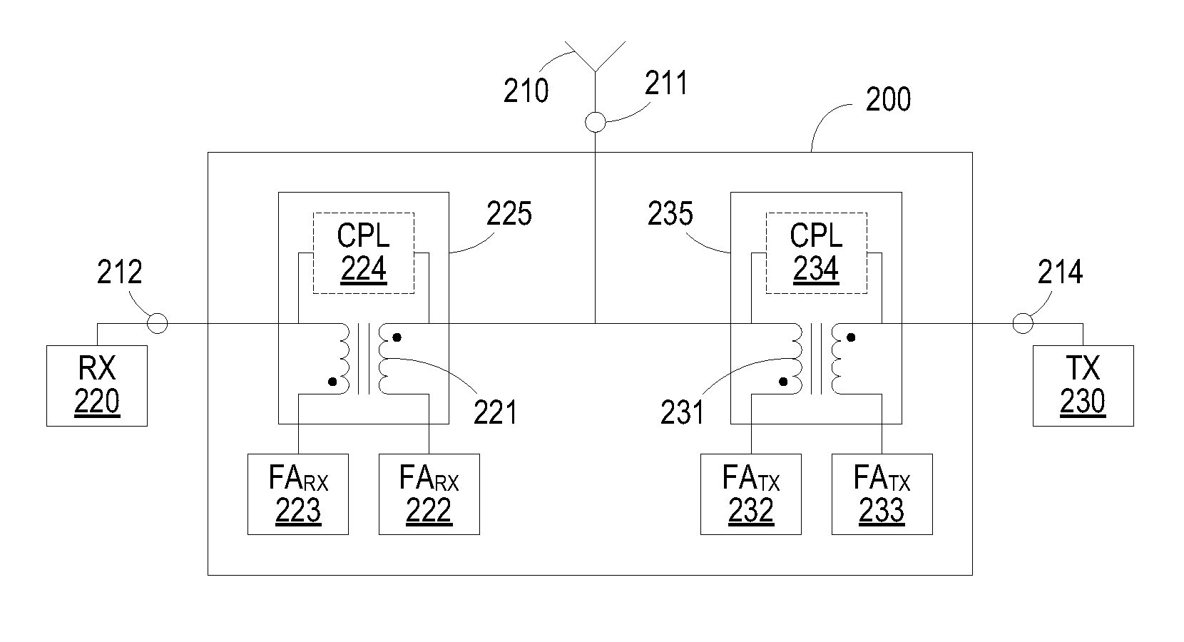
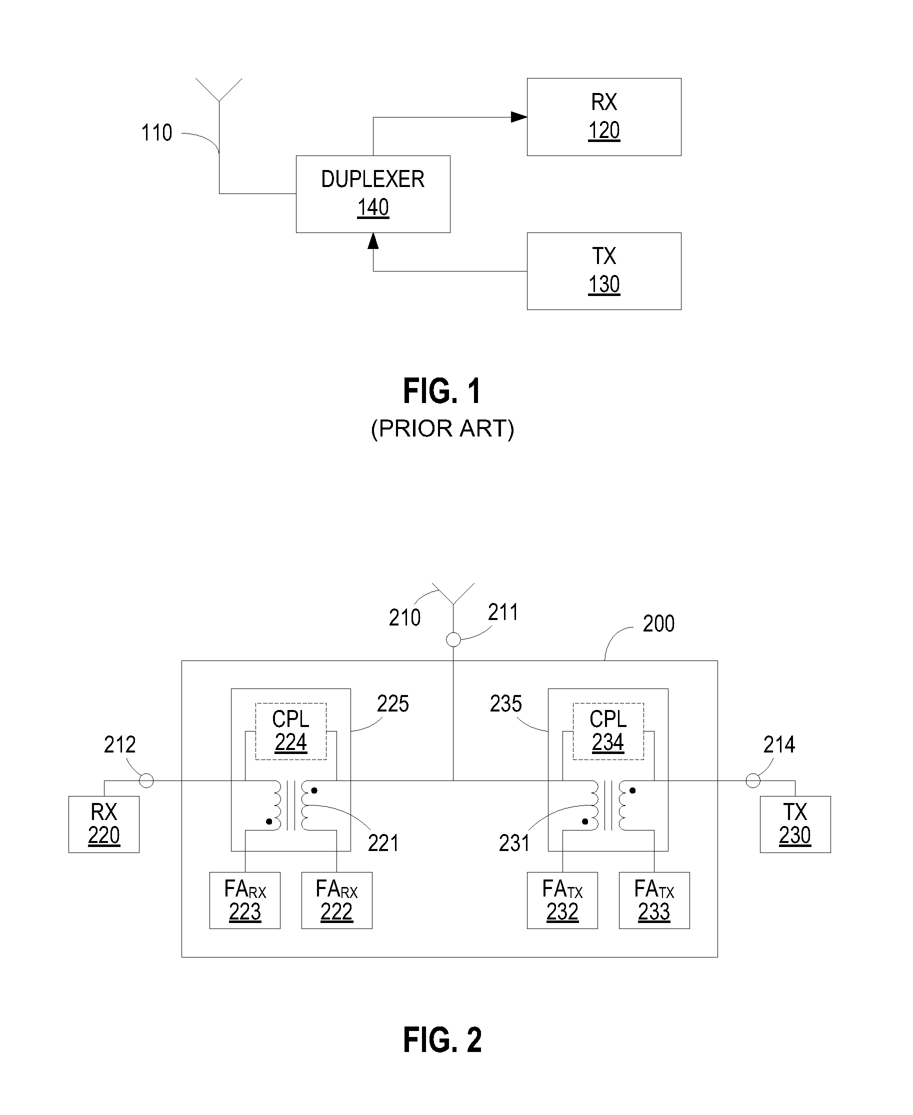
[0057]In the following, embodiments will be described where transceiver structures are provided comprising a receiver, a transmitter, a signal transmission and reception arrangement (e.g., an antenna), a transmit frequency blocking arrangement and a receive frequency blocking arrangement.

[0058]The transmitter is connectable to the signal transmission and reception arrangement node via the receive frequency blocking arrangement and the receiver is connectable to the signal transmission and reception arrangement node via the transmit frequency blocking arrangement.

[0059]The transmit frequency blocking arrangement is adapted to block passage of transmit frequency signals between the signal transmission and reception arrangement and the receiver.

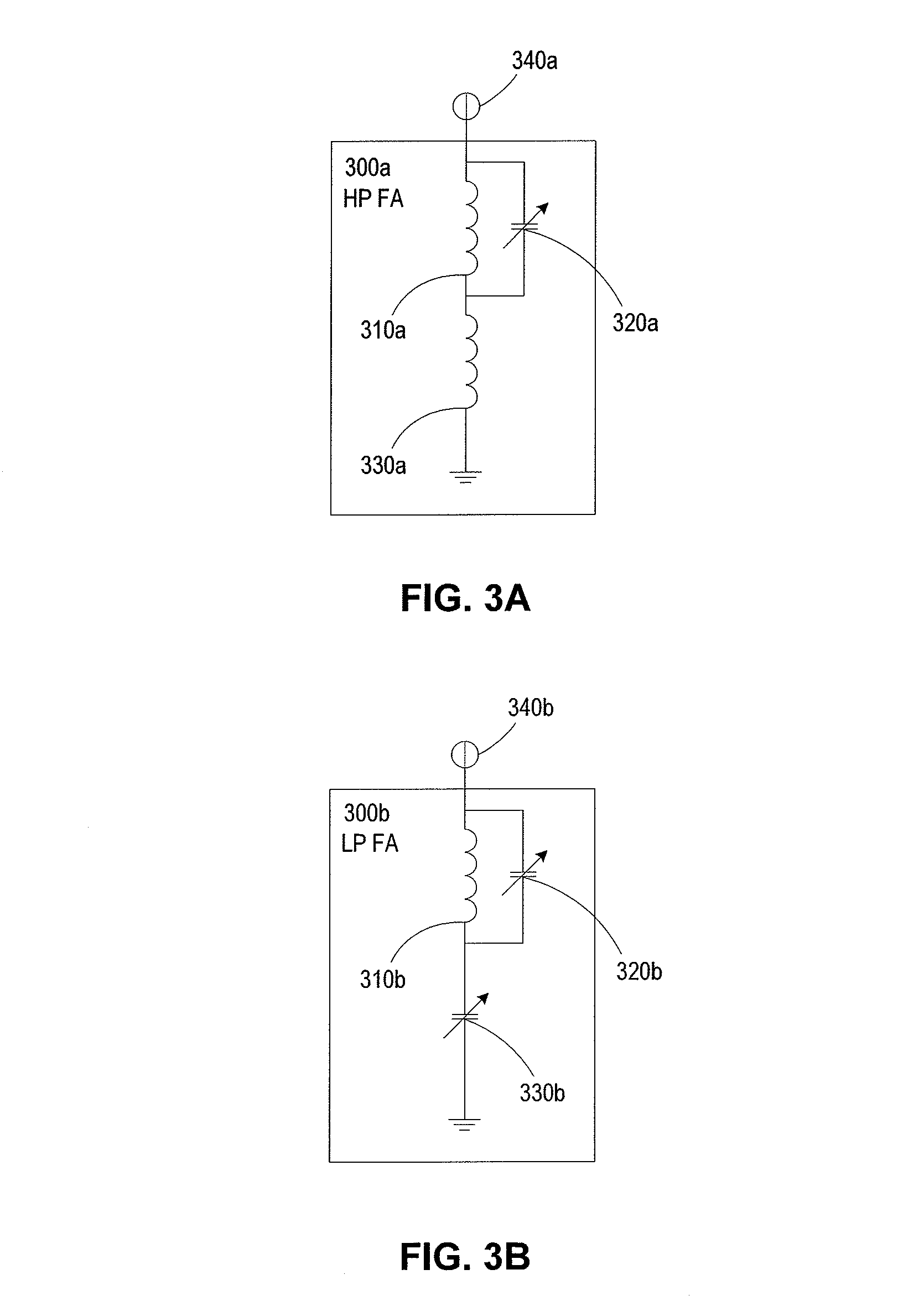
[0060]Blocking of transmit frequency signals may be achieved by the transmit frequency blocking arrangement having a blocking frequency interval associated with the transmit frequency and a non-blocking frequency interval associated with the rec...


PUM

PropertyMeasurementUnit
carrier frequenciesaaaaaaaaaa

Abstract

A transceiver front-end of a communication device comprises a frequency blocking arrangement, which may be either a transmit frequency blocking arrangement or a receive frequency blocking arrangement. The frequency blocking arrangement has a blocking frequency interval associated with one of a transmit frequency and receive frequency, and a non-blocking frequency interval associated with the other of the transmit frequency and receive frequency. The frequency blocking arrangement is configured to block passage of signals in the blocking frequency interval between said signal transmission and reception node and either said receiver node or said transmitter node. The frequency blocking arrangement comprises a network of passive components comprising at least one transformer and a filter arrangement adapted to have a higher impedance value in the blocking frequency interval than in the non-blocking frequency interval.

Description

RELATED APPLICATION[0001]This application claims the benefit under 35 U.S.C. §119 of International Application Number PCT / EP2012 / 063428 filed on Jul. 9, 2012, the disclosure of which is incorporated herein by reference.TECHNICAL FILED[0002]The present invention relates generally to the field of transceiver front-ends for communication devices. More particularly, it relates to transceiver front-ends providing isolation between a transmitter and a receiver.BACKGROUND[0003]In transceivers for frequency division duplex (FDD) communication (e.g., a transceiver of a cellular radio equipment), the receiver typically experiences strong interference signals from the transmitter of the same transceiver.[0004]The interference signal from the transmitter has a carrier frequency at duplex distance from the carrier frequency of the receive signal. A typical duplex distance is small compared to the carrier frequencies. Typically, the duplex distance may be less than 100 MHz while the carrier frequ...

Claims


Application Information

Patent Timeline
Patent Type & Authority Patents(United States)
IPC IPC(8): H03H7/38H04B1/525
CPCH04B1/525H04B2203/5491Y10T29/49117
Inventor DIN, IMAD UDANDERSSON, STEFANECKERBERT, DANIELSJOLAND, HENRIKTIRED, TOBIASWERNEHAG, JOHAN
Owner TELEFON AB LM ERICSSON (PUBL)
Why Eureka
Try Eureka