Drapery tube incorporating batteries within the drapery tube, with a stop for facilitating the loading and unloading of the batteries

a technology of drapery tube and battery, which is applied in the field of drapery tube, can solve the problems of increasing assembly complexity and cost, and achieve the effect of easy replacement or replacemen

a technology of drapery tube and battery, which is applied in the field of drapery tube, can solve the problems of increasing assembly complexity and cost, and achieve the effect of easy replacement or replacemen

US9095907B2Active Publication Date: 2015-08-04CURRENT PROD CORP

Image

  • Drapery tube incorporating batteries within the drapery tube, with a stop for facilitating the loading and unloading of the batteries
  • Drapery tube incorporating batteries within the drapery tube, with a stop for facilitating the loading and unloading of the batteries
  • Drapery tube incorporating batteries within the drapery tube, with a stop for facilitating the loading and unloading of the batteries

Examples


Embodiment Construction

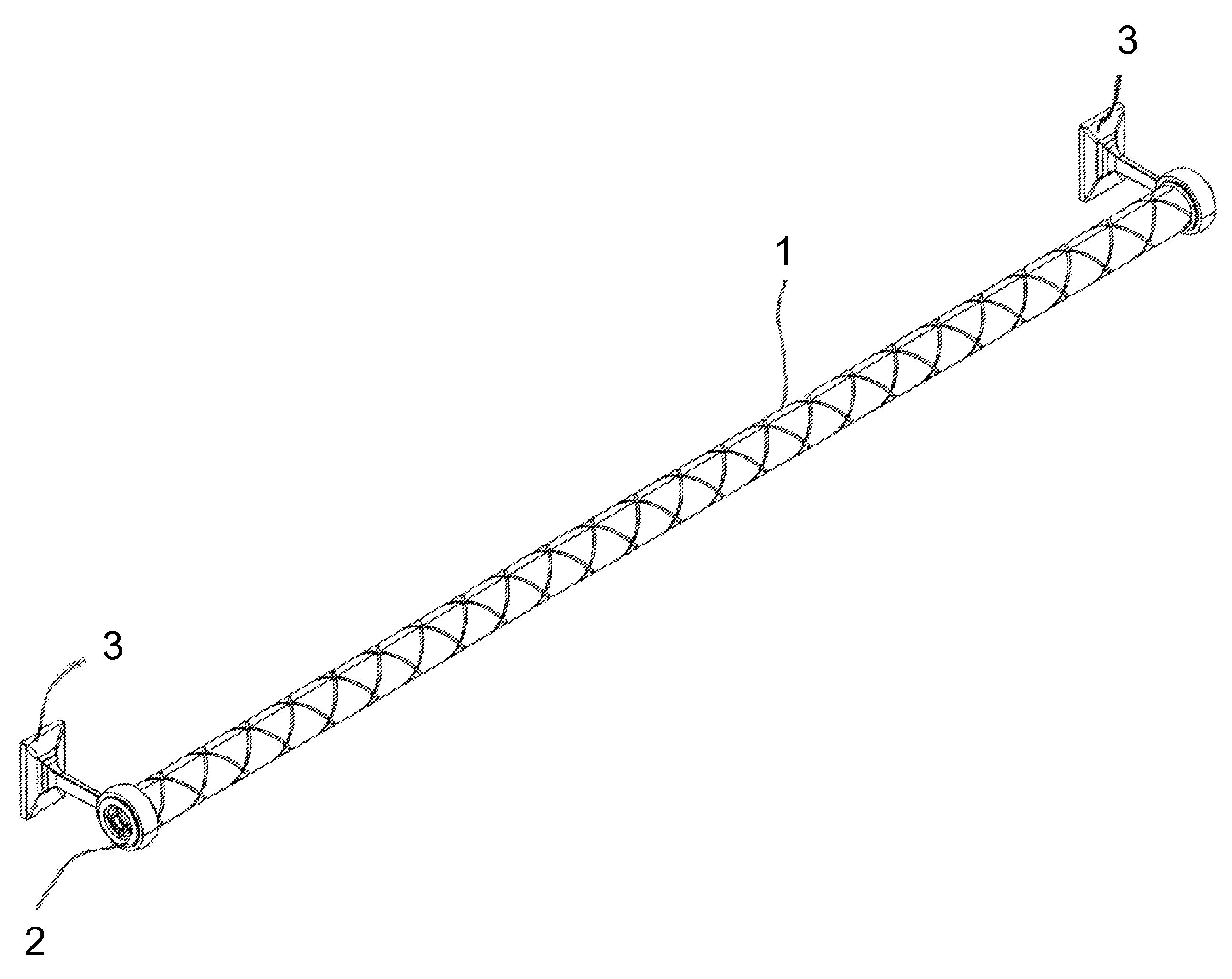
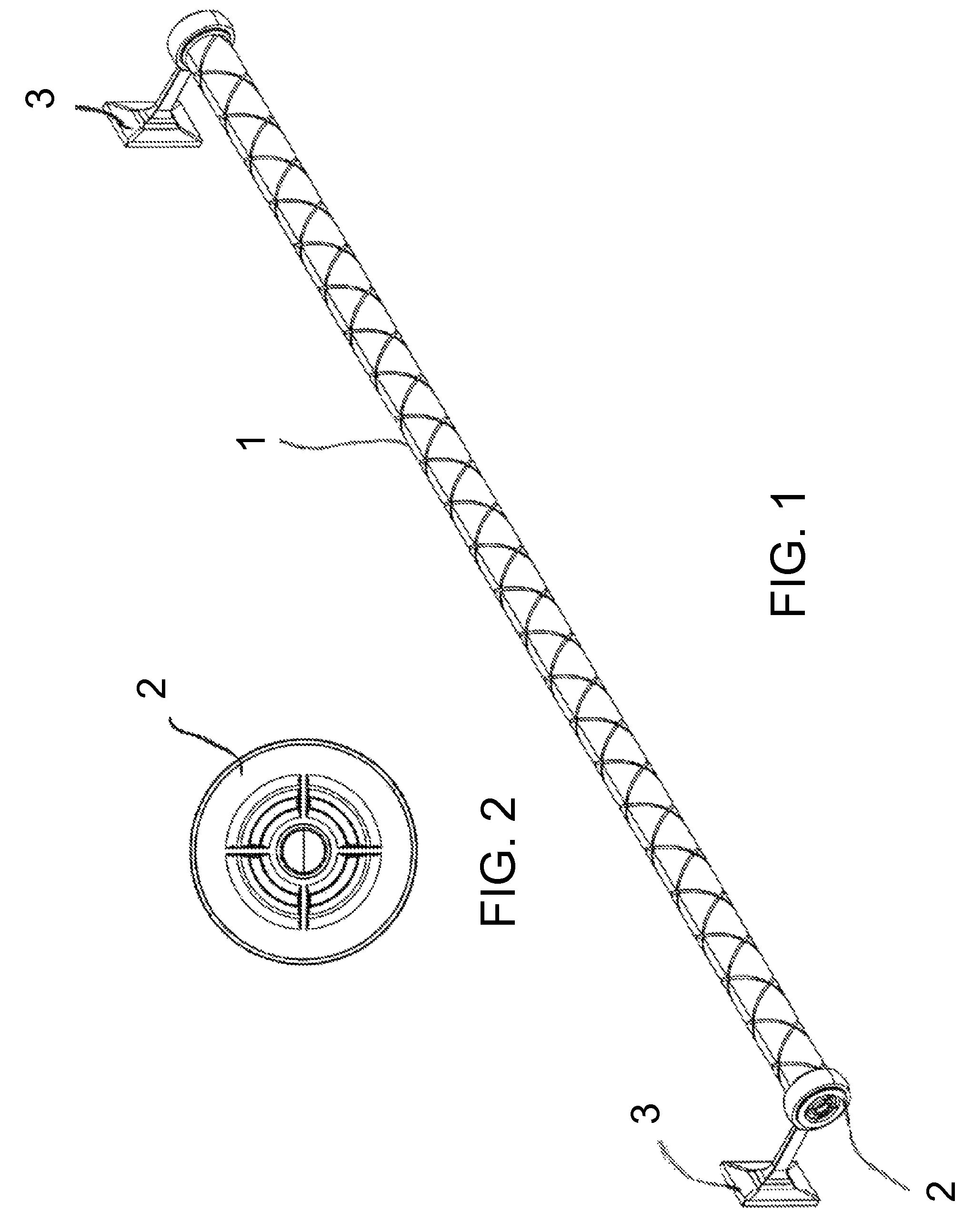
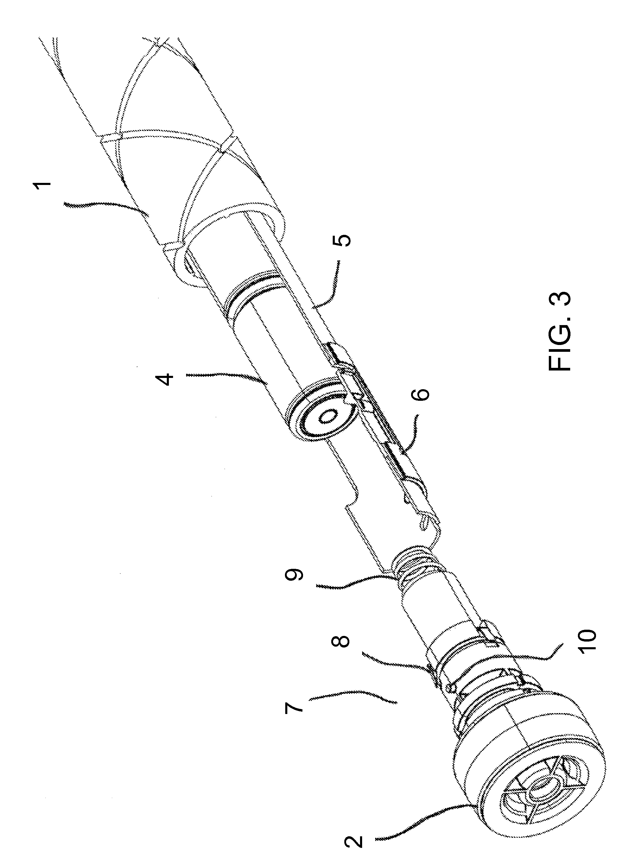
[0031]Specific embodiments will be described in order to illustrate various features that can be incorporated in various embodiments of the subject invention. Referring to FIG. 1 and FIG. 11, the drapery rod or tube 1 is mounted with wall brackets 3 above an opening in a structure such that the drapery can extend and cover the opening. The drapery rod or tube can be motorized for rotating the rod or tube about a longitudinal axis of the rod or tube, and the motor and power supply can be within the rod or tube. In specific embodiments, such as shown in FIG. 1, the motor controls can also be internal to the drapery rod or tube, as taught in U.S. provisional application Ser. No. 61 / 702,093. In specific embodiments, the drapery rod or tube 1 can, optimally, have end caps. The end caps 7 can be plain end caps, and can have compression rings. FIG. 1 shows plain end caps with compression rings 2 and FIG. 11 shows compression rings 2 with finials 23.

[0032]In specific embodiments, the drive ...


PUM

PropertyMeasurementUnit
longitudinal lengthaaaaaaaaaa
forceaaaaaaaaaa
expulsion forceaaaaaaaaaa

Abstract

A motorized window covering is presented having an elongated hollow rod. A battery tube is positioned within the hollow rod. The battery tube has a hollow interior with an elongated spring therein and a stop positioned adjacent an open end of the battery tube. An end cap closes the open end of the battery tube. A plurality of batteries are inserted in end-to-end alignment into the hollow interior of the battery tube. As each battery is inserted, the stop deflects thereby allowing the battery past the stop. Once each battery passes the stop, the stop moves into a stop position thereby holding the battery within the battery tube. To remove each of the plurality of batteries, the stop is deflected and the spring forces the battery out of the hollow interior of the battery tube. The battery tube is electrically connected to a motor that when activated rotates the rod thereby operating the window covering.

Description

BACKGROUND OF INVENTION[0001]Embodiments of the invention relate to a drapery tube that can be used to move curtains or draperies along the tube, incorporating batteries within the drapery tube and a stop for facilitating the load and unloading of the batteries.[0002]There are many types of systems for moving, such as horizontal movement, vertical blind, curtains, and draperies. Some use a series of pulleys, cables, and belts. Others use motors mounted on one end with tracks. In such cases, the number of components adds complexity to the assembly and cost.[0003]U.S. Pat. No. 4,131,831 (Bochenek et al.) teaches a drapery opening and closing system for draw draperies which are movable over a traverse member between an open and closed position by use of a drapery drive system. The opening and closing system has limit switches positioned to be activated when the draperies are opened and closed. A manually settable timer connected to a power source applies power at preset times to a reve...

Claims


Application Information

Patent Timeline
04 Aug 2015
Publication
US9095907B2
IPC
A47H1/00; A47H1/02; B23B1/00; E06B9/72; A47H5/06; A47H23/00; E06B9/40; B23B29/26; B23B3/00; B23B5/08; B23Q1/76
CPC
A47H1/02; E06B9/72; A47H5/06; A47H23/00; E06B9/40; B23B1/00; B23B29/26; B23B3/00
Inventors
MULLET, WILLIS JAY; FOX, MICHAEL D.