Hybrid vehicle clutch control device

a hybrid vehicle and clutch control technology, applied in the field of hybrid vehicle clutch control devices, can solve problems such as large rotation differences, and achieve the effect of improving clutch control accuracy

Inactive Publication Date: 2015-08-04
AISIN SEIKI KK
View PDF12 Cites 2 Cited by
  • Summary
  • Abstract
  • Description
  • Claims
  • Application Information

AI Technical Summary

Benefits of technology

[0005]However, when applying the technology disclosed in the Patent Document 1 to a hybrid vehicle which includes both the engine and the motor / generator (which is a motor generating a drive force to be transmitted to the drive wheels using an electric power accumulated in the battery and regenerating the electric power by being driven by the drive wheels during regeneration operation) at the time of vehicle being running only by the motor torque from the motor / generator, the clutch device is in disengagement state, wherein the engine and a transmission are not connected. If such clutch disengagement state continues for a certain period of time, the operating oil sealed into the communication passage generates thermal expansion or contraction by the change of the ambient temperature. Therefore, even the master cylinder is in non-operated state, the slave cylinder is operated, which may vary the relationship between the clutch actuator operating amount and the clutch torque.
[0007]The present invention was made in consideration with the above problems and the object of the invention is to provide a clutch control device for a hybrid vehicle which can improve clutch control accuracy by temporarily engaging the clutch device in case a clutch disengaged state continues for a longer time than a predetermined time period.
[0005]However, when applying the technology disclosed in the Patent Document 1 to a hybrid vehicle which includes both the engine and the motor / generator (which is a motor generating a drive force to be transmitted to the drive wheels using an electric power accumulated in the battery and regenerating the electric power by being driven by the drive wheels during regeneration operation) at the time of vehicle being running only by the motor torque from the motor / generator, the clutch device is in disengagement state, wherein the engine and a transmission are not connected. If such clutch disengagement state continues for a certain period of time, the operating oil sealed into the communication passage generates thermal expansion or contraction by the change of the ambient temperature. Therefore, even the master cylinder is in non-operated state, the slave cylinder is operated, which may vary the relationship between the clutch actuator operating amount and the clutch torque.
[0005]However, when applying the technology disclosed in the Patent Document 1 to a hybrid vehicle which includes both the engine and the motor / generator (which is a motor generating a drive force to be transmitted to the drive wheels using an electric power accumulated in the battery and regenerating the electric power by being driven by the drive wheels during regeneration operation) at the time of vehicle being running only by the motor torque from the motor / generator, the clutch device is in disengagement state, wherein the engine and a transmission are not connected. If such clutch disengagement state continues for a certain period of time, the operating oil sealed into the communication passage generates thermal expansion or contraction by the change of the ambient temperature. Therefore, even the master cylinder is in non-operated state, the slave cylinder is operated, which may vary the relationship between the clutch actuator operating amount and the clutch torque.

Problems solved by technology

Further, when the clutch disengagement operation time continues for a long time period, the engine receiving no load may generate a shifting shock due to an excessive rise of engine rotation speed (rpm) relative to the input shaft rotation speed (rpm) of the AMT which causes a great difference in rotation therebetween.

Method used


Image

  • Hybrid vehicle clutch control device
  • Hybrid vehicle clutch control device
  • Hybrid vehicle clutch control device

Examples


Embodiment Construction

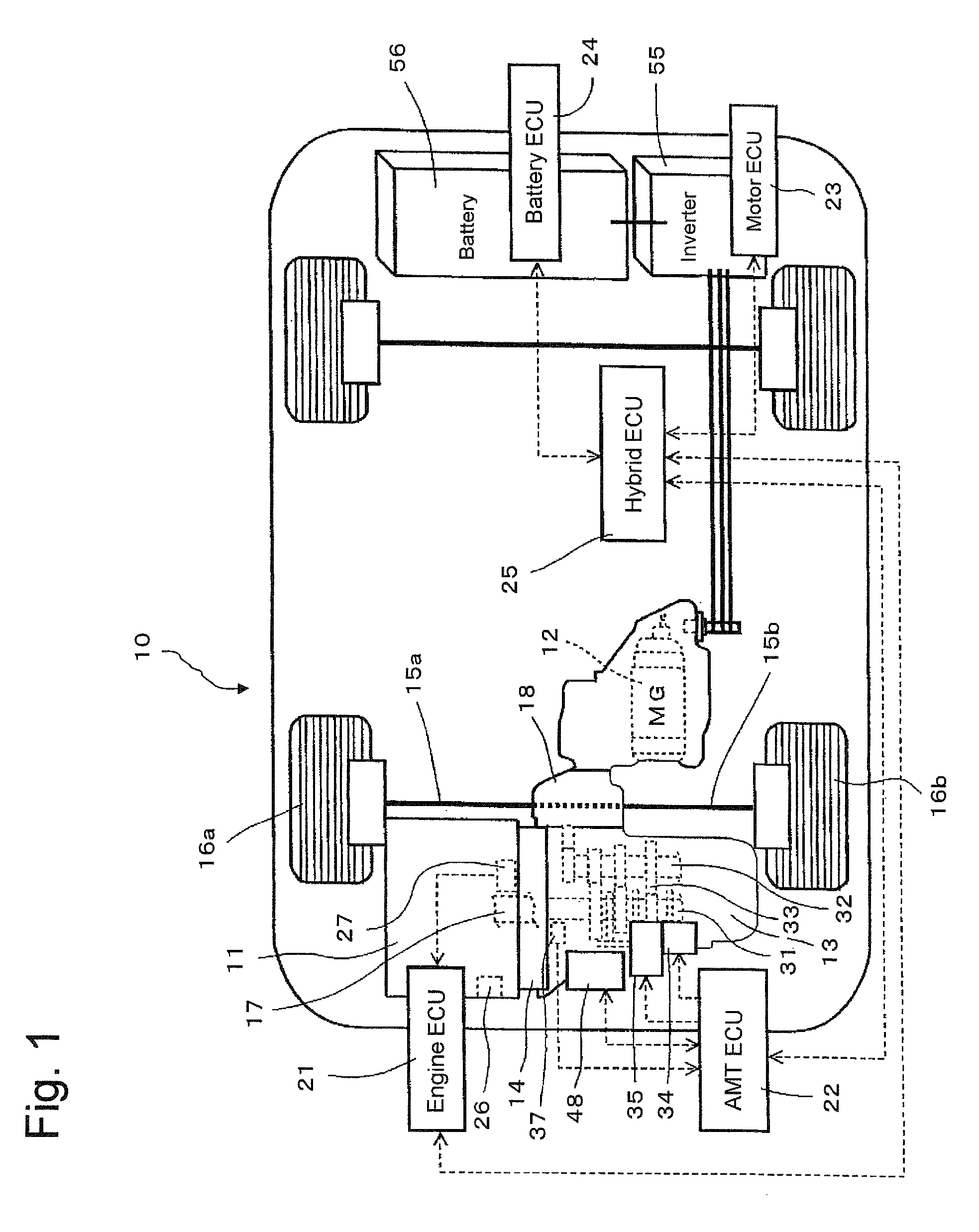
[0015]The embodiments of the clutch control device associated with the present invention will be explained with reference to the attached drawings. In FIG. 1, the hybrid vehicle 10 is provided with an engine 11 as a driving source and a motor / generator 12 (corresponding to the motor of the invention). The drive wheels 16a and 16b of the hybrid vehicle 10 is driven by either one or both of the engine 11 and the motor / generator 12. The hybrid vehicle 10 is further provided with an automated manual transmission 13 and a clutch device 14, etc.

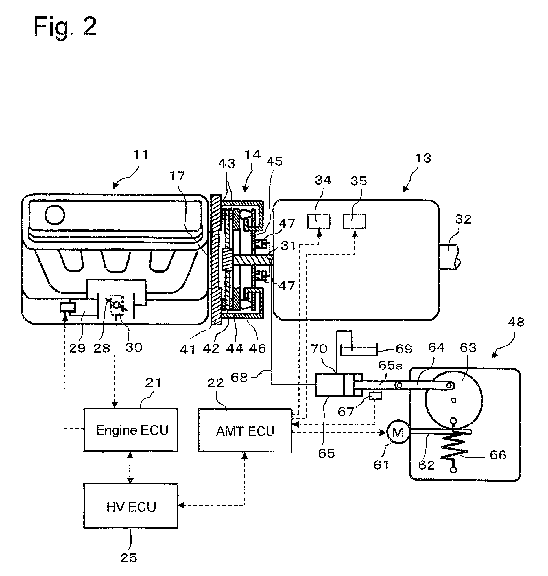
[0016]FIG. 2 is a schematic view of the engine 11, automated manual transmission 13 and the clutch device 14 shown in FIG. 1 and the arrows of the dotted lines connecting the devices indicates the control flow direction.

[0017]The engine 11 is, as shown in FIG. 1, transversally installed in the vehicle at the front side of axle shafts 15a and 15b of the drive wheels 16a and 16b. The engine 11, the clutch device 14 and the automated manual transmissi...


PUM


Abstract

The clutch control device for a hybrid vehicle comprises an engine, an automated manual transmission, a clutch device and a clutch actuator concluding an output rod and a master cylinder which generates a hydraulic pressure therein by closing an idle port in response to the stroke of the output rod, a slave cylinder in fluid communication with the master cylinder through a passage and controlling the clutch device to be in engagement state or disengagement state operated by the hydraulic pressure generated by the master cylinder and a clutch engagement state holding control portion for temporarily holding the clutch device to be in the engagement state by operating the master cylinder to close the idle port after the engagement state under the vehicle being running under a motor drive mode continued for a predetermined time.

Description

TECHNICAL FIELD[0001]This invention relates to a clutch control device for a hybrid vehicle provided with an engine and an automated clutch device to secure the relationship between the clutch actuator operating amount and the clutch torque regardless of the generation of heat expansion or heat contraction of an operating oil.BACKGROUND OF THE TECHNOLOGY[0002]Conventionally, in a vehicle having an engine as a source of driving force, an automated manual transmission (hereinafter referred to as an AMT) has been known. According to the AMT, various actuators are added to an existing manual transmission (gear shifting transmission) for automatically operating a series of gear shifting operations such as clutch engagement / disengagement, gear shifting, gear selecting, in response to an intension or request of an operator of the vehicle or depending on a vehicle running state.[0003]In such AMT, when the clutch is disengaged, first, master cylinder is operated by a clutch actuator, of whic...

Claims


Application Information

Patent Timeline
Patent Type & Authority Patents(United States)
IPC IPC(8): B60W10/02B60L11/14B60L7/14B60L15/20B60K6/48F16D29/00B60W20/00B60K6/547F16D48/02B60L50/16
CPCB60K6/48B60K6/547B60W10/02B60W20/00F16D29/005F16D48/0206B60L7/14B60L11/14B60L15/2009B60L15/2054B60W20/40B60K2006/4808B60Y2400/4242F16D2048/026B60L2210/40B60L2240/12B60L2240/421B60L2240/423B60L2240/441B60L2240/443B60L2240/507B60L2240/80B60L2270/145Y02T10/6221Y02T10/626Y10S903/902Y02T90/16Y02T10/7077Y02T10/7241Y02T10/7275Y02T10/642Y02T10/70Y10T477/26F16D2500/1066F16D2500/30808F16D2500/5016F16D48/066F16D2500/1083F16D2500/3026F16D2500/3067F16D2500/30816F16D2500/3108F16D2500/31426F16D2500/3166F16D2500/7041F16D2500/7044F16D2500/70488B60L50/16Y02T10/62Y02T10/64Y02T10/7072Y02T10/72B60W10/023
Inventor TERAKAWA, TOMOMITSUHOSOI, YASUHIROKITAMURA, YUICHIROSUZUKI, YOSHIHIDE
Owner AISIN SEIKI KK
Why Eureka
Try Eureka